Table of Contents
Advertisement
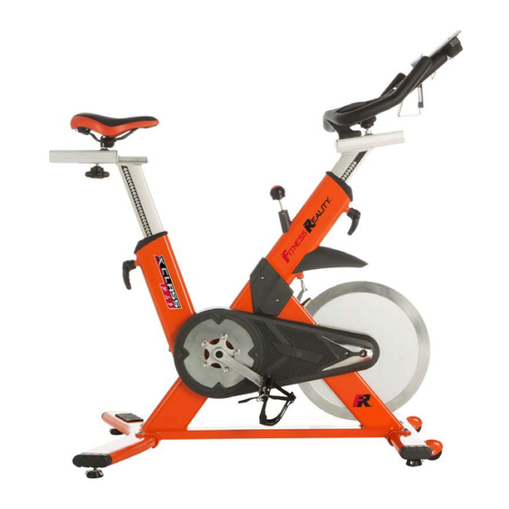
Fitness Reality X-Class 710ST Smart Technology
Indoor Training Cycle
IMPORTANT: Read all instructions carefully before using this product. Retain this
owner's manual for future reference. The specifications of this product may vary from
this photo and is subject to change without notice.
2252.2-110117
2252.1- 030217
Advertisement
Table of Contents

Related Manuals for Fitness Reality X CLASS 710ST


Summary of Contents for Fitness Reality X CLASS 710ST
- Page 1 Fitness Reality X-Class 710ST Smart Technology Indoor Training Cycle IMPORTANT: Read all instructions carefully before using this product. Retain this owner’s manual for future reference. The specifications of this product may vary from this photo and is subject to change without notice.
- Page 2 PLEASE DO NOT RETURN THIS PRODUCT TO THE STORE. STOP. Contact customer service if you have any questions regarding assembly or proper operation of the machine. Email us at: Service@paradigmhw.com Or call us at: 1-844-641-7920 Hours: 8:00 am to 5:00 pm (PST) Daily...
-
Page 3: Table Of Contents
TABLE OF CONTENTS SERVICE---------------------------------------------------------------------------------------------------- 2 LABEL PLACEMENT------------------------------------------------------------------------------------- 3 IMPORTANT SAFETY GUIDELINES---------------------------------------------------------------- 4 OVERVIEW DRAWING------------------------------------------------------------------------------------ 6 HARDWARE & TOOLS PACK------------------------------------------------------------------------ 8 PART LIST--------------------------------------------------------------------------------------------------- 9 ASSEMBLY -------------------------------------------------------------------------------------------- ----- 11 OPERATIONS & ADJUSTMENTS ------------------------------------------------------------------- 20 CONSOLE FUNCTIONS-------------------------------------------------------------------------------- 22 TROUBLESHOOTING & MAINTENANCE---------------------------------------------------------- 24 WARRANTY------------------------------------------------------------------------------------------------ 25 PARTS REQUEST FORM ----------------------------------------------------------------------------- 26... -
Page 4: Service
SERVICE IMPORTANT: FOR NORTH AMERICA ONLY For damaged or defective product, questions, replacement parts or any other service support, please contact our customer service department (8:00 AM - 5:00 PM Pacific Standard Time, Daily) by the below methods: For The Best Service, please Email: service@paradigmhw.com Response Time: 1-2 Business Days Emailing us with the information above will be the best method to receive a response... -
Page 5: Label Placement
LABEL PLACEMENTS... -
Page 6: Important Safety Guidelines
IMPORTANT SAFETY GUIDELINES Read all instructions before using the Indoor Cycle. When using an Indoor Cycle, basic precautions should always be followed, including the following: WARNING - To reduce the risk of injury to persons: Make sure your equipment is correctly assembled before you use it. Be sure all screws, nuts, and bolts are tightened prior to use. - Page 7 IMPORTANT SAFETY GUIDELINES Do not use this equipment if you have any of the following conditions or ailments: • Pregnancy • Extreme obesity • Middle ear infection • Hiatus hernia or Ventral hernia • Glaucoma, retinal detachment or conjunctivitis • Use of anticoagulants including Aspirin in high doses.
-
Page 8: Overview Drawing
OVERVIEW DRAWING... - Page 9 OVERVIEW DRAWING...
-
Page 10: Hardware & Tools Pack
HARDWARE & TOOLS PACK... -
Page 11: Part List
PARTS LIST No. Description No. Description PEDAL(L) HEXAGONAL NUT M8×7(mm) LOWER BRAKE AXLE PEDAL(R) M10×L:55(mm) BRAKE BALANCE BAR HEXAGONAL BOLT BRAKE PAD WASHER ˜10× 20×t2.0(mm) BRAKE BALANCE BUSHING Seat Cushion SPRING 37×20× ˜ 1.5(mm) MAIN FRAME SET BEARING-6004ZZ ˜20× ˜ 42×12 (mm) SPRING ˜15×... - Page 12 PARTS LIST Description Description RUBBER PAD FLYWHEEL BOLT AXLE SLEEVE WASHER WASHER ˜27× ˜ 20.5×t:3(mm) BOLT CHAIN COVER DART-SHAPED COVER CONSOLE PLATE CONSOLE SELF-TAPPING SCREW M3×8(mm) FRONT LEFT COVER BOTTLE HOLDER BOLT WASHER ˜21. 3×t=3.0(mm) HANDLEBAR ADJUSTABLE POST MAGNET˜10× 7(mm) LOWER SLIDE ENDCAP 34L×24.5W×16H(mm) UPPER BRAKE AXLE...
- Page 13 PRE-ASSEMBLY TOOL 6mm Allen Wrench with Phillips Screwdriver 1 PC Pre-Assembly: Remove Front Protection Bar Loosen the Bolts with the 6mm Allen Wrench with Phillips Screwdriver provided and remove the Front Protection Bar from the Main Frame. This bar is used to protect the bracket from deformation during shipping. It will not be used in assembly and should be discarded.
-
Page 14: Assembly
ASSEMBLY STEP 1 1A. Installation of the front stabilizer with wheels Attach the Front Stabilizer Set with Transport Wheels (76) to the Main Frame Set (7) with two Washers (4) and two Hexagonal Bolt (3). Tighten the two bolts using the 6mm Allen Wrench with Phillips Screwdriver until they are both firm and secure. - Page 15 ASSEMBLY Tool (107) Thread Sealant STEP 3 3A. Applying the Thread Sealant Fully coat the threads of both Left (1) & Right Pedals (2) with Thread Sealant (107) before the pedal assembly. Note: Before applying Thread Sealant (107), make sure parts are clean. Allow the sealant to cure for at least 12 hours before use.
- Page 16 ASSEMBLY TOOL 15mm Combination Wrench 1 PC STEP 4 4A. Installing the Left and Right Pedal Note: The Cranks and Pedals are marked “R” for Right and “L” for Left. straight when inserting the pedal. Hand-tighten the pedal shaft in a counter-clockwise ↺ Left Pedal: Insert the Left Pedal (1) into the threaded hole in the Left Crank (12).
- Page 17 ASSEMBLY STEP 5 5A. Console installation Insert 4 AA batteries into the back of the Console (67). Attach the Console (67) to the Console Plate (66). Use the 3mm Allen Wrench to tighten the Console Plate (66) to the Handlebar Set (54) with two Bolts (65).
- Page 18 ASSEMBLY STEP 7 7A. Preassembly to installing the Handlebar Adjustment Post Carefully pull the Styrofoam Block out of the front of the Main Frame Set (7). Underneath the foam will be a twist tie, remove it and tie it to the Speed Sensor Wire (101) that is coming out from the Main Frame Set (7).
- Page 19 ASSEMBLY STEP 8 Securing Handlebar Slide Slide the Handlebar Set (54) onto the Handlebar Adjustable Post (70) in the direction shown to the left. Note: The Hex Screw (29) and Upper Slider End Caps (59) were packaged with this manual. Install the Hex Screw (29) from underneath Handlebar...
- Page 20 ASSEMBLY STEP 9 9A. Linking the sensor wire to the console. Insert the Sensor Wire (100) into the port located underneath the Console (67). Connect the Sensor Wire (100) to the Speed Sensor Wire (101). (100) (101)
- Page 21 ASSEMBLY STEP 10 10A. Securing the seat cushion Insert the Seat Cushion (5) onto the post on top of the Seat Slider (73) and tighten the nuts already on the Seat Cushion (5) using the 13, 14, 15, 17mm Wrench Tool provided to secure the seat in place.
-
Page 22: Operations & Adjustments
OPERATIONS & ADJUSTMENTS Turn the Fixed Handle (27) counter-clockwise ↺ to loosen the Seat Height Adjustment the Fixed Handle (27) clockwise ↻ to secure the seat again. post. Adjust the seat up or down to your desired position. Turn Do not raise the seat post over the STOP line. Turn Adjustable Knob (53) counter-clockwise ↺... - Page 23 OPERATIONS & ADJUSTMENTS Turn the Adjustable Knob (98) clockwise ↻ to increase tension Tension Adjustment Turn Adjustable Knob (98) counter-clockwise ↺ to decrease tension. (98) Emergency Stop Press down on the Adjustable Knob (98) to stop the flywheel. (98) Foot Strap Put your foot as forward as possible into the shoe cage, and then pull the foot strap until it is snug around your shoe to avoid slipping off the pedal.
-
Page 24: Console Functions
CONSOLE FUNCTIONS BUTTON FUNCTION To select training mode and adjust function value up. DOWN To select training mode and adjust function value down. RESET Total Reset. To reboot the console. MODE Confirm setting or selection. DISPLAY FUNCTION TIME Display range 0:00~99:59. DISTANCE Display range 0.00~99.9. - Page 25 CONSOLE FUNCTIONS OPERATING PROCEDURE POWER ON: Start Training by pedaling. MANUAL PROGRAM Set Target Time, Distance and Calories by pressing the MODE button. Note: 1. The console requires four 1.5 Volt AA Alkaline Battery. 2. When user stops pedaling for 4 minutes, the console will enter into sleep mode automatically.
-
Page 26: Troubleshooting & Maintenance
TROUBLESHOOTING & MAINTANENCE TROUBLESHOOTING The console is not working correctly or is not working at all. Be sure to check to that the console cables are all connected securely. Be sure that there is adequate battery life for the console. Refer to our Console Functions page for more information on how to use the console. -
Page 27: Warranty
WARRANTY MANUFACTURER’S LIMITED WARRANTY Paradigm Health & Wellness warrants to the original purchaser that this product is free from defects in material and workmanship when used for the purpose intended, under the conditions that it has been installed and operated in accordance with Paradigm’s Owner’s Manual. Paradigm’s obligation under this warranty applies to the following: COMPONENT LENGTH OF WARRANTY Frame... -
Page 28: Parts Request Form
PARTS REQUEST FORM Paradigm Health & Wellness, Inc. EMAIL THIS FORM WITH YOUR RECEIPT OF PURCHASE TO Service@paradigmhw.com NAME:_____________________________________________________________________________________ ADDRESS:__________________________________________________________________________________ CITY:________________________ STATE:_____________ ZIP:_______________________________________ TELEPHONE: (Day)________________________________________________________________________ (Night)_______________________________________________________________________ SERIAL#:___________________________________________________________________________________ MODEL#:___________________________________________________________________________________ PURCHASE DATE:___________________________________________________________________________ PLACE OF PURCHASE:_______________________________________________________________________ PART # DESCRIPTION “YOUR ORDER WILL BE PROCESSED WITHIN 3 BUSINESS DAYS” This form can also be faxed in Fax #: 626-810-2166...
Need help?
Do you have a question about the X CLASS 710ST and is the answer not in the manual?
Questions and answers