Table of Contents
Advertisement
Quick Links
Advertisement
Table of Contents

Related Manuals for Woodland Mills BANDSAW BLADE SHARPENER


Summary of Contents for Woodland Mills BANDSAW BLADE SHARPENER
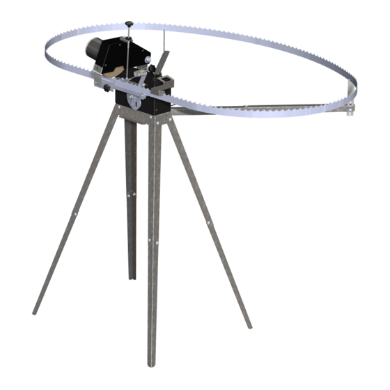
- Page 1 BANDSAW BLADE SHARPENER OPERATOR’S MANUAL...
-
Page 3: Table Of Contents
Sharpener Operator’s Manual TABLE OF CONTENTS TABLE OF CONTENTS ____________________________________________ INTRODUCTION __________________________________________________ KEY SYMBOLS ___________________________________________________ SAFETY REGULATIONS ___________________________________________ TECHNICAL SPECIFICATIONS ______________________________________ OVERALL DIMENSIONS _________________________________________ ASSEMBLY ______________________________________________________ 1. TOOLS REQUIRED __________________________________________ 2. MOUNTING STYLE __________________________________________ 3. STAND ____________________________________________________ A. LEGS ______________________________________________________ B. - Page 4 Sharpener Operator’s Manual BACK AND HOOK ANGLES ____________________________________ PROFILING THE GRINDING DISC ________________________________ FUSES ______________________________________________________ OPERATION ____________________________________________________ 1. SETTING THE HOOK ANGLE _________________________________ 2. INSTALLING THE BLADE ____________________________________ A. BLADE SUPPORTS ________________________________________ B. BACK REST _______________________________________________ C. PRESSURE PLATE _________________________________________ 3.
-
Page 5: Introduction
INTRODUCTION This operator’s manual describes in detail Symbols and warning signs shown on this how the bandsaw blade sharpener is used page can be found in this operator’s manual and maintained and how servicing is to be and on the sharpener. -
Page 6: Safety Regulations
Sharpener Operator’s Manual SAFETY REGULATIONS The following safety regulations apply to the sharpener: • Do not store gasoline/petrol in the vicinity of the sharpener. Sparks from the grinding disc or the electrical connection could ignite it. • The bandsaw blade is sharp and can cause injury. Always wear protective gloves when handling blades. -
Page 7: Overall Dimensions
Sharpener Operator’s Manual OVERALL DIMENSIONS BBS-MY2020-EN: Rev A Page 19-May-2020... -
Page 8: Assembly
Sharpener Operator’s Manual ASSEMBLY 1. TOOLS REQUIRED Tool Specification Screwdriver T20 Torx Wrench/Socket 8 mm Wrench/Socket 10 mm Pliers Min. 2 in [50 mm] grip dia BBS-MY2020-EN: Rev A Page 19-May-2020... -
Page 9: Mounting Style
Sharpener Operator’s Manual 2. MOUNTING STYLE Before starting the assembly decide how the sharpener will be mounted when in use. If utilizing the stand is desirable from a portability standpoint, proceed to the next section, STAND. However, if the sharpener would be better utilized secured to a workbench, skip over the STAND section and start at assembly step, CONTROL BOX. -
Page 10: Stand
Sharpener Operator’s Manual 3. STAND Using the hardware and components listed below, assemble the stand. If the sharpener will be mounted directly to a workbench, skip this assembly step and proceed to the next section. M5 X 12 mm M6 Flat Carriage Bolt Washer M5 Hex Nut... -
Page 11: Legs-To-Mounting Base (Front)
Sharpener Operator’s Manual B. LEGS-TO-MOUNTING BASE (FRONT) With all the legs assembled, fasten the front legs to the mounting base using the following hardware on each leg: two (2) M5 X 12 mm carriage bolts, two (2) M6 flat washers, one (1) M5 lock nut, and one (1) M5 wing nut. -
Page 12: Legs-To-Mounting Base (Rear)
Sharpener Operator’s Manual C. LEGS-TO-MOUNTING BASE (REAR) Fasten the rear legs to the mounting base using the following hardware on each leg: four (4) M5 X 12 mm carriage bolts, four (4) M6 flat washers, four (4) M5 hex nuts. Rear face of mounting base has slots for support arms. - Page 13 Sharpener Operator’s Manual The completed stand should now look as shown: BBS-MY2020-EN: Rev A Page 19-May-2020...
-
Page 14: Control Box
Sharpener Operator’s Manual 4. CONTROL BOX Using the hardware and components listed below, assemble the control box to the stand and the advancer to the control box. M6 X 14 mm Control Box Hex Bolt Sub-Assembly Advancer M6 Hex Nut Sub-Assembly A. -
Page 15: Advancer
Sharpener Operator’s Manual B. ADVANCER Then assemble the advancer sub-assembly to the connecting arm on the control box using one (1) M6 hex nut. Snug the nut but do not over-tighten. BBS-MY2020-EN: Rev A Page 19-May-2020... -
Page 16: Grinding Head
Sharpener Operator’s Manual 5. GRINDING HEAD Begin the grinding head assembly by using the hardware listed below to assemble the grinding head sub-assembly to the control box. M10 X 40 mm Grinding Head Knob Sub-Assembly M10 Flat Washer A. GRINDING HEAD-TO-CONTROL BOX Assemble the grinding head to the rear of the control box using the M10 X 40 mm knob and M10 flat washer. -
Page 17: Grinding Disc
Sharpener Operator’s Manual B. GRINDING DISC Next, assembly the grinding disc to the grinding head sub-assembly. Grinding Disc Remove the knurled nut from the electric motor and slide the grinding disc onto the shaft. Replace the nut and tighten it securely using pliers. Remove knurled nut from motor before installing grinding disc. -
Page 18: Depth Adjustment Rod
Sharpener Operator’s Manual C. DEPTH ADJUSTMENT ROD Using the hardware listed below, assemble the depth adjustment rod to the grinding head. Depth M6 Hex Nut Adjustment M6 Thru-Hole M6 Acorn Nut Lock Knob M6 Threaded Knob Thread the long-threaded end of the rod up through the bracket on the grinding head. Then thread the thru-hole lock knob, the M6 hex nut, and the upper knob to the top of the rod. -
Page 19: Grinding Shield
Sharpener Operator’s Manual D. GRINDING SHIELD To finalize the grinding head assembly, secure the grinding shield to the grinding head using the hardware listed below. #8 X 0.375 Torx Self- Grinding Shield Tapping Screw Using a T20 Torx screwdriver, secure the shield to the grinding head as shown. BBS-MY2020-EN: Rev A Page 19-May-2020... -
Page 20: Support Arms
Sharpener Operator’s Manual 6. SUPPORT ARMS A. INNER SUPPORT ARMS Using the hardware and components listed below, assemble the inner support arms to the sharpener. M6 4-Lobe Inner Support Knob Facing the rear of the sharpener, slide the right inner support arm into the cutout in the mounting base. -
Page 21: Outer Support Arms
Sharpener Operator’s Manual B. OUTER SUPPORT ARMS Using the hardware and components listed below, assemble the outer support arms to the sharpener. M5 X 12 mm Cotter Pin Carriage Bolt 626-2RS M5 Hex Nut Bearing Outer Support M5 Wing Nut M6 Flat Blade Support Washer... -
Page 22: Workbench Mounting (Optional)
Sharpener Operator’s Manual 7. WORKBENCH MOUNTING (OPTIONAL) If it is desirable to mount the sharpener to a workbench instead of utilizing the stand, be sure the M6 X 14 mm hex bolt was used in place of the the 4-lobe knob in step, INNER SUPPORT ARMS, on page 16. -
Page 23: Battery
Sharpener Operator’s Manual BATTERY The customer is required to purchase their own 12 Volt battery. 12 V Battery Follow the battery polarity label on top of the control box: connect the POSITIVE clamp (+ red) to the positive battery terminal and the NEGATIVE clamp (— black) to the negative battery terminal. -
Page 24: Maintenance
Sharpener Operator’s Manual MAINTENANCE The bandsaw blade should be set and sharpened regularly for optimal performance. During normal sawing of most wood species this should be done at intervals of approximately 2 hours of effective cutting time (effective cutting time refers to the time the bandsaw blade was actually cutting). -
Page 25: Sharpening Guidelines
Sharpener Operator’s Manual SHARPENING GUIDELINES The more accurate the sharpening, the straighter and smoother the bandsaw blade runs when cutting the log. GULLET RADII The radius in the gullet area “R” (FIG 2) should be 0.04 to ⅛ in [1 to 3 mm]. A radius under 0.04 in [1 mm] increases the risk of cracking. -
Page 26: Profiling The Grinding Disc
Sharpener Operator’s Manual PROFILING THE GRINDING DISC The grinding disc must have the correct profile prior to sharpening a blade. Use the grinding disc profile template and whetstone shown in the table below to shape the disc. Grinding Disc Profiling Whetstone Template **Note: do not shape the grinding disc using the profiling template. - Page 27 Sharpener Operator’s Manual The sharpener ships with a new grinding disc with a square profile. This and any replacement discs will require profiling before sharpening a blade. Remove a little material at a Grinding disc profile is Use the whetstone to time with the whetstone while square out of the box.
-
Page 28: Fuses
Sharpener Operator’s Manual FUSES The sharpener uses two (2) fuses of differing amperage: 0.5 A and 15 A. A spare for each is provided. 0.5 A Fuse 15 A Fuse The 0.5 A fuse is located inside the connector that is inline with the wiring harness and the 15 A fuse is inside connector on the positive (red) battery clamp cable. -
Page 29: Operation
Sharpener Operator’s Manual OPERATION 1. SETTING THE HOOK ANGLE Loosen the large knob on the back of the control box and rotate the grinding head to set the appropriate hook angle for the blade to be sharpened. Once set, tighten the locking knob. The detent in the grinding head shaft seats into one of the 3 predefined lock points in... -
Page 30: Installing The Blade
Sharpener Operator’s Manual 2. INSTALLING THE BLADE A. BLADE SUPPORTS First, seat the far side of the blade into the notches on each of the blade supports. Keep the weld seam left of the grinding disc so it does not interfere with the setup process. -
Page 31: Back Rest
Sharpener Operator’s Manual B. BACK REST Position the near side of the blade so it slides down between the back rest and large washers. Rotate the advancer up when installing the blade on the control box. C. PRESSURE PLATE Tighten the knob on the pressure plate until it bottoms out. The blade should slide left-but not move in or out (forwards or backwards). -
Page 32: Calibrating The Advancement
Sharpener Operator’s Manual 3. CALIBRATING THE ADVANCEMENT A. CONNECT THE BATTERY Before connecting the battery ensure both toggle switches are set to STOP. Follow the battery polarity label on top of the control box: connect the POSITIVE clamp (+ red) to the positive battery terminal and the NEGATIVE clamp (—... -
Page 33: Advance The Blade
Sharpener Operator’s Manual B. ADVANCE THE BLADE Turn the advancer control on and allow the advancer to move the blade by two (2) teeth. Advancer toggle switch on **If the cam is turning clockwise, turn off the machine and reverse the battery polarity.** Turn off the toggle switch once the advancer has pushed the second tooth’s hook face as far to the left as it will go and the lever is at its highest position. -
Page 34: Rotate The Grinding Head Down
Sharpener Operator’s Manual C. ROTATE THE GRINDING HEAD DOWN Manually rotate the grinding head down—do not turn it on. Seat the acorn nut at the end of the depth adjustment rod into the hole in the stop plate. Seat acorn nut into hole in stop plate. - Page 35 Sharpener Operator’s Manual Turn the advancer on and observe the movement of the grinding disc relative to the tooth profile. Do not turn the grinding head on. Keep a free hand on the motor housing in case the grinding disc hits the blade and the head needs to be Turn the advancer knob...
-
Page 36: Fine-Tune The Advancement
Sharpener Operator’s Manual D. FINE-TUNE THE ADVANCEMENT One half of the adjustment setting is fine-tuning the advancement so that the left face of the grinding disc is flush with the hook face of the tooth. Use the advancer knob to adjust how far the blade is pushed to the left. Turning it clockwise will push the blade farther to the left while counter-clockwise will back off the advancer and reduce the blade's leftward movement. -
Page 37: Fine-Tune The Grinding Head Movement
Sharpener Operator’s Manual E. FINE-TUNE THE GRINDING HEAD MOVEMENT The other half of the adjustment setting is fine-tuning the grinding head height so that the bottom of the grinding disc touches the bottom of the tooth gullet. Turn upper knob clockwise to raise the head, counter- clockwise to lower it... - Page 38 Sharpener Operator’s Manual As the disc leaves the gullet it should completely clear the next tooth’s back angle profile. If the blade tooth profile has a steep back angle, adjust the position of the stop plate by flipping up the lever and loosening the M5 socket head cap screw and lock nut. This adjustment will allow the grinding disc to clear the tooth as it exits the gullet.
-
Page 39: Sharpening
Sharpener Operator’s Manual 4. SHARPENING With the machine now setup for the blade to be sharpened, follow the steps below to begin sharpening the teeth. A. ADVANCE THE BLADE Lift the grind head and while holding the advancer up, manually pull the blade back through until the weld seam is right of the grinding disc. -
Page 40: Set Grind Depth
Sharpener Operator’s Manual B. SET GRIND DEPTH Rotate the grinding head down and seat the acorn nut in the stop plate hole. Turn on both the advancer and grinder toggle switches. Make small adjustments to the advancer and depth adjustment rod to achieve a light grinding sound where approximately 0.004-0.008 in [0.1-0.2 mm] is being removed. -
Page 41: Position The Auto-Stop
Sharpener Operator’s Manual C. POSITION THE AUTO-STOP Attach the auto-stop to the blade to automatically stop the sharpener once all the teeth have been ground. Auto-Stop It is important to correctly position the auto-stop in order to stop the sharpener before the blade weld seam reaches the grinding head. - Page 42 Sharpener Operator’s Manual When the auto-stop is positioned correctly it triggers the toggle switches just before the blade weld seam reaches the grinding disc. The auto-stop triggers the toggle switches, shutting off the sharpener. Manually grind last tooth. Weld seam ~ 7 in [178 mm] AUTO-STOP ACTIVATED The last tooth can be ground manually by moving the blade and lowering the grinding head by...
-
Page 43: Storage
Sharpener Operator’s Manual STORAGE The sharpener footprint can be reduced significantly by folding the front legs back. It can then be stored up against a wall or, hung from it, or fit in the back of a vehicle for easier transport. Remove both support arms first. -
Page 44: Parts List
Sharpener Operator’s Manual PARTS LIST Item Part No. Description 0001557 UPPER LEG 0001558 LOWER LEG 0001554 MOUNTING BASE 0003815 CONTROL BOX FRONT COVER 0003816 MOUNTING ARM SHAFT 0003817 BRONZE BUSHING, 12 mm OD, 10 mm BORE 0003818 CONNECTING ARM SHAFT 0003819 GEARMOTOR, 8 mm DIA SHAFT 0003820... - Page 45 LABEL, BLADE ANGLE 0004112 LABEL, PRODUCT INFO 0004113 LABEL, QUALITY CONTROL 0004114 LABEL, WOODLAND MILLS W/ ROTATION ARROW 0004115 LABEL, MADE IN SWEDEN 626-2RS BALL BEARING, SEALED, 626-2RS, 6mm BORE, 19mm OD, 6mm WIDE 6000-2RS BALL BEARING, SEALED, 6000-2RS, 10 mm BORE, 26 mm OD, 8 mm WIDE HEX BOLT, M5 X 0.8, 10 mm LG...
-
Page 46: Exploded Assembly Views
Sharpener Operator’s Manual EXPLODED ASSEMBLY VIEWS STAND BBS-MY2020-EN: Rev A Page 19-May-2020... -
Page 47: Control Box
Sharpener Operator’s Manual CONTROL BOX BBS-MY2020-EN: Rev A Page 19-May-2020... -
Page 48: Grinding Head
Sharpener Operator’s Manual GRINDING HEAD BBS-MY2020-EN: Rev A Page 19-May-2020... -
Page 49: Control Head To Stand
Sharpener Operator’s Manual CONTROL HEAD TO STAND BBS-MY2020-EN: Rev A Page 19-May-2020... -
Page 50: Accessories And Labels
Sharpener Operator’s Manual ACCESSORIES AND LABELS BBS-MY2020-EN: Rev A Page 19-May-2020... -
Page 51: Notes
Sharpener Operator’s Manual NOTES BBS-MY2020-EN: Rev A Page 19-May-2020... - Page 52 Sharpener Operator’s Manual BBS-MY2020-EN: Rev A Page 19-May-2020...
- Page 53 Sharpener Operator’s Manual BBS-MY2020-EN: Rev A Page 19-May-2020...
- Page 54 Sharpener Operator’s Manual BBS-MY2020-EN: Rev A Page 19-May-2020...
Need help?
Do you have a question about the BANDSAW BLADE SHARPENER and is the answer not in the manual?
Questions and answers
What’s the amp draw on the blade sharpener? Looking at a 110v to 12v transformer.