Woodland Mills HM122 Operator's Manual
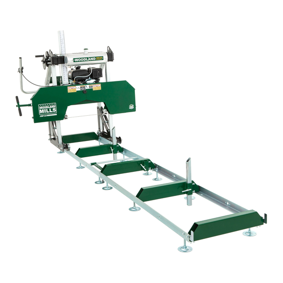
Portable sawmill
Hide thumbs
Also See for HM122:
- Operator's manual (108 pages) ,
- Owner's manual (52 pages) ,
- Assembly instructions manual (20 pages)
Table of Contents
Advertisement
Quick Links
Advertisement
Table of Contents

Related Manuals for Woodland Mills HM122


Summary of Contents for Woodland Mills HM122
- Page 1 HM122 PORTABLE SAWMILL OPERATOR’S MANUAL...
- Page 2 This page intentionally left blank.
-
Page 3: Table Of Contents
HM122 Operator’s Manual TABLE OF CONTENTS TABLE OF CONTENTS _________________________________________________________ INTRODUCTION _______________________________________________________________ INTENDED USE _______________________________________________________________ SAFETY GUIDELINES __________________________________________________________ WORK AREA _______________________________________________________________ INTERNAL COMBUSTION ENGINE SAFETY _____________________________________ PERSONAL SAFETY ________________________________________________________ TOOL USE AND CARE _______________________________________________________ EQUIPMENT OPERATION ____________________________________________________ MAINTENANCE _____________________________________________________________ TECHNICAL SPECIFICATIONS... - Page 4 HM122 Operator’s Manual GREASING THREADS _______________________________________________________ ENGINE OIL ________________________________________________________________ DIRECTION OF CUT ___________________________________________________________ SAWMILL SET-UP PROCEDURES _______________________________________________ BELT TENSION ____________________________________________________________ BLADE TRACKING _________________________________________________________ REDUCING BLADE TENSION _________________________________________________ ADJUSTING THE FOLLOWER SIDE (RIGHT SIDE) _______________________________ BLADE GUIDE ADJUSTMENT ________________________________________________ FRONT POST ADJUSTMENT...
-
Page 5: Introduction
For technical questions and replacement parts, please contact Woodland Mills Inc. INTENDED USE Woodland Mills wood sawmills are designed for acreage owners to aid in the milling of natural, untreated wood with the mill firmly supported on the ground. Materials that are processed may contain chemicals or by-products that could corrode the machine or damage it, resulting in safety concerns. -
Page 6: Safety Guidelines
HM122 Operator’s Manual SAFETY GUIDELINES **SAVE THESE INSTRUCTIONS** WARNING! Read and understand all instructions. Failure to follow all instructions listed below may result in electric shock, fire, and/or serious injury. WARNING! The warnings, cautions, and instructions discussed in this instruction manual cannot cover all possible conditions or situations that could occur. -
Page 7: Work Area
HM122 Operator’s Manual WORK AREA Keep work area clean, free of clutter and well lit. Cluttered and dark work areas can • cause accidents. Do not use your sawmill where there is a risk of causing a fire or an explosion; e.g. in •... -
Page 8: Personal Safety
HM122 Operator’s Manual PERSONAL SAFETY • Stay alert, watch what you are doing and use common sense when operating a power tool. Do not use a power tool when you are tired or under the influence of drugs, alcohol, or medication. -
Page 9: Tool Use And Care
HM122 Operator’s Manual TOOL USE AND CARE Always be sure the operator is familiar with proper safety precautions and operation • techniques before using machine. Never touch the engine or muffler while the engine is on or immediately after it has been •... -
Page 10: Equipment Operation
HM122 Operator’s Manual EQUIPMENT OPERATION Wear heavy-duty work gloves, ANSI-approved goggles behind a full face shield, steel-toed work boots, and a dust mask. Operate only with assistance. Cut-off branches from the lumber to be processed. Place the lumber to be cut on the track supports. -
Page 11: Maintenance
HM122 Operator’s Manual MAINTENANCE Proper and routine maintenance is critical to operator safety, achieving good milling results, and to prolong the life of your investment. Band Wheel Bearings — Inspect before use to ensure they are not worn. Bearings are •... -
Page 12: Technical Specifications
HM122 Operator’s Manual TECHNICAL SPECIFICATIONS Item Specification 7 hp Kohler Command Pro Gasoline Engine 22 ” (559 mm) Log Diameter Capacity Log Length Capacity 10’4” (3150 mm) Distance Between Blade Guides 18” (457 mm) Maximum Cut Depth 6" (152 mm) Last Cut Off Deck 1”... -
Page 13: Overall Dimensions
HM122 Operator’s Manual OVERALL DIMENSIONS HM122-MY2019: Rev A Page 05-Dec-2018... -
Page 14: Assembly
HM122 Operator’s Manual ASSEMBLY 1. TOOLS REQUIRED TOOL SPECIFICATION Wrench/Socket 7 mm (2X) Wrench/Socket 10 mm (2X) Wrench/Socket 13 mm (2X) Wrench/Socket 14 mm (2X) Wrench/Socket 15 mm (2X) Wrench/Socket 16 mm (2X) Wrench/Socket 17 mm (2X) Wrench/Socket 18 mm (2X) -
Page 15: Unpacking
HM122 Operator’s Manual 2. UNPACKING Unpack the contents of the crate except for the saw head and the two long boxes in the bottom that contain the sections of track. Unfasten the two (2) M8 bolts/nuts on the front of the crate using a socket/wrench. -
Page 16: Track
HM122 Operator’s Manual 3. TRACK Assemble the track system with the provided components and hardware listed in the table below. It is important to assemble and level the track on a firm foundation before tightening all of the hardware and it should ideally be a minimum of 4” (100 mm) off the ground. This will allow for easy cleanup of sawdust from under the tracks and height adjustment of the log supports. - Page 17 HM122 Operator’s Manual The track comes completely disassembled from the factory. Lay out all the components on a flat piece of level ground prior to assembly. See the TRACK exploded view for a more detailed part breakdown. HM122-MY2019: Rev A...
- Page 18 HM122 Operator’s Manual When assembling the log bunks to the rails, ensure that the two end bunks are square (90°) as shown in Figure 1. Use sixteen (16) M10 X 25 mm bolts at both end bunks and the two(2) mid bunks excluding the mid bunk at the rail joint (Figures 1 &...
- Page 19 HM122 Operator’s Manual Assemble the four (4) carriage stops to the ends of the rails using eight (8) M10 X 25 mm bolts and tighten. Ensure carriage stops are assembled to the inside face of the rails, not the outside (Figure 4).
-
Page 20: Log Clamp And Supports
HM122 Operator’s Manual 4. LOG CLAMP AND SUPPORTS Assemble the log clamp components as shown below. Attach the completed assembly to the track using four (4) M10 X 25 mm bolts with lock nuts and tighten. Log Clamp M8 X 20 mm... - Page 21 HM122 Operator’s Manual Attach both log dog assemblies to the track as shown below using the two (2) nuts and bolts provided. Note that there are various locations along the track where the log dogs can be bolted. Depending on how many track sections are being used, select a log clamp position that will secure the log firmly against the log supports.
-
Page 22: Sawmill Head Assembly
HM122 Operator’s Manual 5. SAWMILL HEAD ASSEMBLY The sawmill head assembly is built in multiple steps. Follow the steps in the sub-sections below using the parts tables at the top of each sub-section to gather the necessary components and hardware for each step. - Page 23 HM122 Operator’s Manual Install the M6 X 16 mm hex bolt into the threaded hole near the top of the inside of the left post as shown below. This will act as a stop for the saw head so it is not raised too high during operation.
-
Page 24: Carriage Legs
HM122 Operator’s Manual CARRIAGE LEGS The carriage leg sub-assemblies come loosely assembled from the factory. Final tightening of these bolts will be done in a later step. See the CARRIAGE LEG, WHEEL, AND SWEEPER exploded view for a more detailed part breakdown. - Page 25 HM122 Operator’s Manual Slide the carriage legs and posts up until they stop at the post sleeves on the saw head. With the help of another person, stand the saw head assembly upright. HM122-MY2019: Rev A Page 05-Dec-2018...
-
Page 26: Rear H-Frame
HM122 Operator’s Manual REAR H-FRAME Use the components listed below to install the rear H-frame to the carriage legs. The H-frame comes pre-assembled with the valve and its housing bolted to the back side. M12 X 80 mm Hex Bolt... -
Page 27: Cross Beam
HM122 Operator’s Manual CROSS BEAM With the hardware listed below, assemble the cross beam to the carriage posts. M12 X 70 mm Cross Beam Hex Bolt Assembly M12 X 31 mm Cross Beam Fender Mounting Washer Plate End Cap Using a socket/wrench and the help of... - Page 28 HM122 Operator’s Manual Use a mallet to assemble the four (4) plastic end caps into the tops of both front posts and the rear H- frame. HM122-MY2019: Rev A Page 05-Dec-2018...
-
Page 29: Lift Cable Routing
HM122 Operator’s Manual LIFT CABLE ROUTING The wire rope lift cable listed below comes pre-assembled to the winch. Lift Cable Route the lift cable as shown in the steps below. [Engine removed from some views for clarity.] Cable crimp joint Lift cable comes pre- assembled to winch. - Page 30 HM122 Operator’s Manual Attach loop of shorter Attach loop of cable end to bolt long cable located at left side of end to oval band wheel housing chain link on right side. Be sure to securely tighten the oval chain link nut with a wrench after the cable loop ends have been attached.
-
Page 31: Lubricant Tank
HM122 Operator’s Manual LUBRICANT TANK With the hardware listed below, assemble the lubricant tank, bracket, and heat shield to the left side of the cross beam. M8 X 20 mm Lubricant Tank Hex Bolt M8 Flat Lubricant Tank Washer Bracket... -
Page 32: Lubricant Tubing
HM122 Operator’s Manual LUBRICANT TUBING Use the tubing listed in the table below to complete the routing for the lubrication system. Tubing: Valve- Tubing: Tank- to-Guide to-Valve Block Insert the tank-to-valve tubing into the tank valve w h i l e s i m u l t a n e o u s l y... - Page 33 HM122 Operator’s Manual Continue routing the tubing d o w n w a r d , p a s s i n g i t through the hole in the bracket located at the top of the right-side carriage Finally, connect the tubing...
-
Page 34: Log Scale
HM122 Operator’s Manual LOG SCALE With the hardware listed below, assemble the log scale components. M6 X 30 mm Log Scale Hex Bolt Bracket Log Scale M6 Lock Nut Indicator M6 Flat Magnetic Scale Washer [Yellow] M6 Lock Magnetic Scale... - Page 35 HM122 Operator’s Manual Using two (2) sockets/wrenches, bolt the log scale bracket with two (2) M6 X 16 mm bolts and M6 lock nuts to the post sleeve as shown below. Attach the clear log scale indicator to the front right post using two (2) M6 X 16 mm hex bolts, M6 flat washers, and M6 lock washers.
-
Page 36: Push Handle
HM122 Operator’s Manual PUSH HANDLE With the components listed below, assemble the push handle to the rear H-frame. Push Handle T-Handle Push Handle End Cap Fit an end cap into each end of the push handle and slide it through the two large holes at the top of the rear H-frame. - Page 37 HM122 Operator’s Manual Leave approximately 3-¾ in [95 mm] between the first hole and H-frame post HM122-MY2019: Rev A Page 05-Dec-2018...
-
Page 38: Throttle Handle And Cable
HM122 Operator’s Manual THROTTLE HANDLE AND CABLE Use the hardware listed below to assemble the throttle handle and route the throttle cable. M6 X 55 mm Throttle Hex Bolt Handle M6 X 50 mm Throttle Cable Hex Bolt Bracket M4 X 12 mm... - Page 39 HM122 Operator’s Manual Route the throttle cable around the front of the right post and behind the lift cable hook as shown below. With the throttle lever in the idle position (fully open), slide the throttle cable stop bushing over the end of the cable sheath and pull the cable tight at the engine.
-
Page 40: Placing The Saw Head On The Track
HM122 Operator’s Manual 6. PLACING THE SAW HEAD ON THE TRACK LIFTING THE SAW HEAD ASSEMBLY At least two people are required for this step. Start by removing the two (2) carriage stops from one end of the track. The head can be walked over to the track until positioned behind it (Figure 1). -
Page 41: Rolling The Sawmill Head Assembly
HM122 Operator’s Manual ROLLING THE SAWMILL HEAD ASSEMBLY Roll the sawmill head assembly along the full length of the track to ensure it moves freely. If it binds or is difficult to push it is likely the track is not square, straight, and/or level. Make the necessary adjustments to the track and roll the head assembly again. -
Page 42: Levelling The Sawmill Head Assembly
HM122 Operator’s Manual LEVELLING THE SAWMILL HEAD ASSEMBLY Using a tape measure, measure the distance from the blade to the top of the log bunk on both the left and right side. The distance must be equal. If the measurements are not equal, adjust the lift cable hook end to either raise or lower the right side until it matches the left. -
Page 43: Band Wheel Door Latches
HM122 Operator’s Manual BAND WHEEL DOOR LATCHES Using the hardware listed below, assemble the three (3) band wheel door latches. M4 X 14 mm Phillips Flat Latch Spacer Head Screw M4 X 10 mm Phillips Flat Latch Head Screw M4 Lock Nut One (1) latch is installed at the centre of the top of the band wheel housing and the remaining two (2) along the bottom. - Page 44 HM122 Operator’s Manual Using a Phillips head screwdriver and a socket/wrench, assemble the upper latch to the band wheel housing and the catch to the top flange of the ride-side band wheel door. Use five (5) M4 X 10 mm Phillips flat head screws and M4 lock nuts for both parts.
-
Page 45: Greasing Threads
HM122 Operator’s Manual GREASING THREADS Add waterproof grease to the threads of the blade tension handle and to the mating washer face prior to use. Proper blade tension is achieved using a toque wrench with a 24 mm socket and torquing the tension handle to 25 ft•lb (34 N•m). -
Page 46: Engine Oil
HM122 Operator’s Manual ENGINE OIL Refer to the engine manual before using your sawmill. Please note that the engine does not contain any gasoline or oil when it is shipped. Furthermore, the engine is equipped with an oil alert system, meaning that if the crankcase oil level is low or empty, the power is cut to the spark plug and it will not start. -
Page 47: Direction Of Cut
HM122 Operator’s Manual DIRECTION OF CUT Always cut in the direction shown below. The log clamps are located to the right side of the log and the log supports on the left. Failure to cut in this direction can cause the log to come loose and possibly cause damage or injury. -
Page 48: Sawmill Set-Up Procedures
HM122 Operator’s Manual SAWMILL SET-UP PROCEDURES BELT TENSION Follower Belt: Polyurethane belt that seats tightly in the V-groove around the right-side band wheel. No adjustment is required for this belt. Drive Belt: BX64 fibre-impregnated cogged V-belt that runs between the left-side band wheel and clutch housing pulley on the engine. - Page 49 HM122 Operator’s Manual With the engine free to slide on the mounting plate, turn the nut on the horizontal stud in the clockwise direction. This will pull the engine towards the stud and apply more tension on the belt. Do this step incrementally while checking the belt for proper deflection. It is also important to ensure that the engine remains perpendicular to the drive belt.
-
Page 50: Blade Tracking
HM122 Operator’s Manual BLADE TRACKING Never attempt to adjust the blade tracking with the engine running. As a safety precaution, remove the spark plug cap. Gloves and safety glasses should be worn when working with the blade as it is extremely sharp. -
Page 51: Reducing Blade Tension
HM122 Operator’s Manual REDUCING BLADE TENSION Loosen the blade guide holder assembly bolt using a socket/wrench. The round shaft should now be free to slide rearward and out of the way. Perform this step on both blade guide assemblies. This ensures the guide bearings will not influence the tracking of the blade whilst being adjusted. -
Page 52: Adjusting The Follower Side (Right Side)
HM122 Operator’s Manual ADJUSTING THE FOLLOWER SIDE (RIGHT SIDE) Loosen the tracking alignment locking nut with a 24 mm wrench or an adjustable wrench. The alignment bolt can now be turned to change the angle of the band wheel and track the blade. - Page 53 **Never attempt to adjust the drive side (left side) blade tracking without contacting Woodland Mills first. This is set from the factory and should not be adjusted.** HM122-MY2019: Rev A Page...
-
Page 54: Blade Guide Adjustment
HM122 Operator’s Manual BLADE GUIDE ADJUSTMENT Never attempt to adjust the guide blocks or the guide bearing with the engine running. As a safety precaution, remove the spark plug cap. It is also advised to confirm that the blade is tracking properly before performing the steps below. - Page 55 HM122 Operator’s Manual Using feeler gauges or thick pieces of paper (.020” / 0.5 mm), place them between the blade and both the upper & lower guide blocks, and then tighten the set screws. .020” (0.5 mm) gap [Top and bottom faces of blade] .040”...
-
Page 56: Front Post Adjustment
HM122 Operator’s Manual FRONT POST ADJUSTMENT There are four (4) nylon bolts, two on each post sleeve—top & bottom—that control how loose or tight the saw head slides up-and-down the front posts. Snug the bolts to the posts only finger-tight so that the saw head does not struggle when making vertical height adjustments between cuts. -
Page 57: Sawmill Maintenance
HM122 Operator’s Manual SAWMILL MAINTENANCE BLADE TENSION Proper blade tension is achieved using a torque wrench with a 24 mm socket to torque the tension handle to 25 ft•lb (34 N•m). Ensure the belleville washers are oriented and installed as shown in the picture below. -
Page 58: Changing The Blade
HM122 Operator’s Manual CHANGING THE BLADE Never attempt to change the blade with the engine running. As a safety precaution, remove the spark plug cap. Gloves and safety glasses must be worn when changing the blade. Remove the blade tension by turning the tension handle counter-clockwise. -
Page 59: Replacing Belts
Gloves and safety glasses must be worn when replacing the belts. There are two V-belts on the sawmill. It is recommended to to use a BX64 cogged belt for the drive side and a Woodland Mills polyurethane belt on the follower side. Polyurethane Follower Belt... - Page 60 HM122 Operator’s Manual To change the drive side belt, loosen the four bolts that secure the engine to its mount using two (2) sockets/wrenches. Now that the engine is free to slide on the mounting plate, turn the nut on the horizontal stud (located beneath the engine on the right side) in a counter-clockwise direction.
- Page 61 HM122 Operator’s Manual The old drive belt can now be removed and the new belt installed. Tension the new belt and refer to the BELT TENSION instructions described in the SAWMILL SET-UP PROCEDURES section of the manual. The follower belt is changed by prying it off and installing the new one with the aid of a slotted screwdriver.
-
Page 62: Troubleshooting
HM122 Operator’s Manual TROUBLESHOOTING Problem/Issue Possible Causes Resolution Options 1. Inadequate blade tension. 1. Tighten blade. Refer to page 55. 2. Improper blade guide set 2. Gap between guide blocks and blade are incorrect. Refer to page 52. Producing wavy 3. -
Page 63: Parts List
HM122 Operator’s Manual PARTS LIST Item Part No. Description 0001459 TRACK RAIL 0001457 LOG BUNK, END 0001458 LOG BUNK 0001463 REINFORCEMENT PLATE 0001055 CARRIAGE STOP 0001460 LOG CLAMP CONNECTING ROD 0001461 LOG CLAMP ARM 0001462 LOG CLAMP 0001056 LOG SUPPORT, LONG... - Page 64 HM122 Operator’s Manual Item Part No. Description 0001474 CROSS BEAM MOUNTING PLATE 0001470 PUSH HANDLE 0001660 PLASTIC END CAP, RECT, 50 X 50 mm 0001662 PLASTIC END CAP, CIRCULAR, 32 mm OD 0001021 THROTTLE HANDLE 0001514 THROTTLE CABLE BRACKET 0001515...
- Page 65 HM122 Operator’s Manual Item Part No. Description HEX BOLT, M12 X 1.75, 45 mm LG HEX BOLT, M12 X 1.75, 70 mm LG, 30 mm LG THD HEX BOLT, M12 X 1.75, 80 mm LG, 30 mm LG THD HEX BOLT, M12 X 1.75, 100 mm LG, 30 mm LG THD HEX BOLT, M12 X 1.75, 120 mm LG, 30 mm LG THD...
-
Page 66: Exploded Assembly Views
HM122 Operator’s Manual EXPLODED ASSEMBLY VIEWS TRACK HM122-MY2019: Rev A Page 05-Dec-2018... -
Page 67: Back Beam
HM122 Operator’s Manual BACK BEAM HM122-MY2019: Rev A Page 05-Dec-2018... -
Page 68: Guide Blocks A & B
HM122 Operator’s Manual GUIDE BLOCKS A & B HM122-MY2019: Rev A Page 05-Dec-2018... -
Page 69: Saw Head
HM122 Operator’s Manual SAW HEAD HM122-MY2019: Rev A Page 05-Dec-2018... -
Page 70: Band Wheel Housing
HM122 Operator’s Manual BAND WHEEL HOUSING HM122-MY2019: Rev A Page 05-Dec-2018... -
Page 71: Band Wheel Housing Doors
HM122 Operator’s Manual BAND WHEEL HOUSING DOORS HM122-MY2019: Rev A Page 05-Dec-2018... -
Page 72: Band Wheels
HM122 Operator’s Manual BAND WHEELS HM122-MY2019: Rev A Page 05-Dec-2018... -
Page 73: Engine
HM122 Operator’s Manual ENGINE HM122-MY2019: Rev A Page 05-Dec-2018... -
Page 74: Carriage
HM122 Operator’s Manual CARRIAGE HM122-MY2019: Rev A Page 05-Dec-2018... -
Page 75: Carriage Leg, Wheel, And Sweeper
HM122 Operator’s Manual CARRIAGE LEG, WHEEL, AND SWEEPER HM122-MY2019: Rev A Page 05-Dec-2018... -
Page 76: Lift Winch
HM122 Operator’s Manual LIFT WINCH HM122-MY2019: Rev A Page 05-Dec-2018... -
Page 77: Throttle Handle
HM122 Operator’s Manual THROTTLE HANDLE 131 2X 125 2X 131 2X 125 2X HM122-MY2019: Rev A Page 05-Dec-2018... -
Page 78: Notes
HM122 Operator’s Manual NOTES HM122-MY2019: Rev A Page 05-Dec-2018... - Page 79 This page intentionally left blank.
Need help?
Do you have a question about the HM122 and is the answer not in the manual?
Questions and answers