Woodland Mills HM126 Operator's Manual
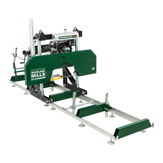
Portable sawmill
Hide thumbs
Also See for HM126:
- Operator's manual (116 pages) ,
- Owner's manual (44 pages) ,
- Manual (16 pages)
Table of Contents
Advertisement
Quick Links
Advertisement
Table of Contents

Subscribe to Our Youtube Channel
Related Manuals for Woodland Mills HM126


Summary of Contents for Woodland Mills HM126
- Page 1 HM126 PORTABLE SAWMILL 9.5 and 14 Horsepower Models OPERATOR’S MANUAL...
- Page 2 This page intentionally left blank.
-
Page 3: Table Of Contents
2018MCE-2019 HM126 Operator’s Manual TABLE OF CONTENTS TABLE OF CONTENTS _________________________________________________________1 INTRODUCTION _______________________________________________________________3 INTENDED USE _______________________________________________________________3 SAFETY GUIDELINES __________________________________________________________4 WORK AREA _______________________________________________________________5 INTERNAL COMBUSTION ENGINE SAFETY _____________________________________5 PERSONAL SAFETY ________________________________________________________6 TOOL USE AND CARE _______________________________________________________7 EQUIPMENT OPERATION ____________________________________________________8 MAINTENANCE_____________________________________________________________9 TECHNICAL SPECIFICATIONS __________________________________________________10... - Page 4 2018MCE-2019 HM126 Operator’s Manual LEVELLING THE SAWMILL HEAD ASSEMBLY __________________________________41 THROTTLE HANDLE AND CABLE _____________________________________________42 GREASING THREADS _______________________________________________________45 BAND WHEEL DOOR LATCHES _______________________________________________46 ROLLING THE SAWMILL HEAD ASSEMBLY ____________________________________47 7. ENGINE _______________________________________________________________48 ENGINE OIL ________________________________________________________________48 SAWMILL SET-UP PROCEDURES _______________________________________________49 BELT TENSION ____________________________________________________________49...
-
Page 5: Introduction
For technical questions and replacement parts, please contact Woodland Mills Inc. INTENDED USE Woodland Mills wood sawmills are designed for acreage owners to aid in the milling of natural, untreated wood with the mill firmly supported on the ground. Materials that are processed may contain chemicals or by-products that could corrode the machine or damage it, resulting in safety concerns. -
Page 6: Safety Guidelines
2018MCE-2019 HM126 Operator’s Manual SAFETY GUIDELINES **SAVE THESE INSTRUCTIONS** WARNING! Read and understand all instructions. Failure to follow all instructions listed below may result in electric shock, fire, and/or serious injury. WARNING! The warnings, cautions, and instructions discussed in this instruction manual cannot cover all possible conditions or situations that could occur. -
Page 7: Work Area
2018MCE-2019 HM126 Operator’s Manual WORK AREA Keep work area clean, free of clutter and well lit. Cluttered and dark work areas can • cause accidents. Do not use your sawmill where there is a risk of causing a fire or an explosion; e.g. in •... -
Page 8: Personal Safety
2018MCE-2019 HM126 Operator’s Manual PERSONAL SAFETY • Stay alert, watch what you are doing and use common sense when operating a power tool. Do not use a power tool when you are tired or under the influence of drugs, alcohol, or medication. -
Page 9: Tool Use And Care
2018MCE-2019 HM126 Operator’s Manual TOOL USE AND CARE Always be sure the operator is familiar with proper safety precautions and operation • techniques before using machine. Never touch the engine or muffler while the engine is on or immediately after it has been •... -
Page 10: Equipment Operation
2018MCE-2019 HM126 Operator’s Manual EQUIPMENT OPERATION Wear heavy-duty work gloves, ANSI-approved goggles behind a full face shield, steel-toed work boots, and a dust mask. Operate only with assistance. Cut-off branches from the lumber to be processed. Place the lumber to be cut on the track supports. -
Page 11: Maintenance
2018MCE-2019 HM126 Operator’s Manual MAINTENANCE Proper and routine maintenance is critical to operator safety, achieving good milling results, and to prolong the life of your investment. Band Wheel Bearings — Inspect before use to ensure they are not worn. Bearings are •... -
Page 12: Technical Specifications
2018MCE-2019 HM126 Operator’s Manual TECHNICAL SPECIFICATIONS The HM126 sawmill comes in two variants: the HM126-9.5 that utilizes a 9.5 horsepower engine and the HM126-14 with a 14 horsepower engine. Both versions are assembled and operated in the same manner. Item HM126-9.5 Specification... -
Page 13: Overall Dimensions
2018MCE-2019 HM126 Operator’s Manual OVERALL DIMENSIONS 0001626-M-EN: Rev A Page 01-Dec-2021... -
Page 14: Assembly
2018MCE-2019 HM126 Operator’s Manual ASSEMBLY 1. TOOLS REQUIRED TOOL SPECIFICATION Wrench/Socket 7 mm (2X) Wrench/Socket 10 mm (2X) Wrench/Socket 13 mm (2X) Wrench/Socket 14 mm (2X) Wrench/Socket 15 mm (2X) Wrench/Socket 16 mm (2X) Wrench/Socket 17 mm (2X) Wrench/Socket 18 mm (2X) -
Page 15: Unpacking
2018MCE-2019 HM126 Operator’s Manual 2. UNPACKING Unpack the contents of the crate except for the saw head and the two long boxes in the bottom that contain the sections of track. Unfasten the two (2) M8 bolts/nuts on the front of the crate using a socket/wrench. -
Page 16: Track
2018MCE-2019 HM126 Operator’s Manual 3. TRACK Assemble the track system with the provided components and hardware listed in the table below. It is important to assemble and level the track on a firm foundation before tightening all of the hardware and it should ideally be a minimum of 4” (100 mm) off the ground. This will allow for easy cleanup of sawdust from under the tracks and height adjustment of the log supports. - Page 17 2018MCE-2019 HM126 Operator’s Manual The track comes completely disassembled from the factory. Lay out all the components on a flat piece of level ground prior to assembly. See the TRACK exploded view for a more detailed part breakdown. 0001626-M-EN: Rev A...
- Page 18 2018MCE-2019 HM126 Operator’s Manual When assembling the log bunks to the rails, ensure that the two end bunks are square (90°) as shown in Figure 1. Use sixteen (16) M10 X 25 mm bolts at all end bunk and mid bunk locations (Figures 1 &...
- Page 19 2018MCE-2019 HM126 Operator’s Manual Attach the twelve (12) levelling feet to the track at the locations shown below. The bolt can be turned to either raise or lower the foot to adjust the level of the track (Figure 4). If setting the track on wooden blocks, use wood screws in the four holes to secure each foot in place.
-
Page 20: Log Clamp And Supports
2018MCE-2019 HM126 Operator’s Manual 4. LOG CLAMP AND SUPPORTS Assemble the log clamp components as shown below. Attach the completed assembly to the track using four (4) M10 X 25 mm bolts with lock nuts and tighten. M10 X 25 mm... - Page 21 2018MCE-2019 HM126 Operator’s Manual Attach log dog assembly to track as shown below with the four (4) nuts and bolts provided. Note that there are various locations along the track where this assembly can be bolted. Depending on how many track sections are being used, select a log clamp position that will secure the log firmly against the log supports.
- Page 22 2018MCE-2019 HM126 Operator’s Manual Clamp should be tilted forward towards log. Insert log supports into track cross supports and secure with T-handles as shown in the picture below. The T-handle threads should be coated with grease. The sawmill includes two sets of log supports—a short set and a long set.
-
Page 23: Sawmill Head Assembly
2018MCE-2019 HM126 Operator’s Manual 5. SAWMILL HEAD ASSEMBLY The sawmill head assembly is built in multiple steps. Follow the sub-sections below using the parts table at the top of each sub-section to gather the necessary components for each step. FRONT POSTS Front Post With the saw head resting approximately 6”... -
Page 24: Carriage Legs
2018MCE-2019 HM126 Operator’s Manual CARRIAGE LEGS The carriage leg sub-assemblies come loosely assembled from the factory. Final tightening of these bolts will be done in a later step. See the CARRIAGE LEG, WHEEL, AND SWEEPER exploded view for a more detailed part breakdown. - Page 25 2018MCE-2019 HM126 Operator’s Manual With the help of another person, stand the saw head upright. 0001626-M-EN: Rev A Page 01-Dec-2021...
-
Page 26: Rear Posts
2018MCE-2019 HM126 Operator’s Manual REAR POSTS Using two (2) sockets/wrenches, attach the rear posts between the carriage leg plates using only one (1) M12 X 80 mm bolt, flat washer, and lock nut per post. Be sure the rear post with the extra holes through the side is assembled on the right-side of the saw head. -
Page 27: Cross Beam
2018MCE-2019 HM126 Operator’s Manual CROSS BEAM With the hardware listed below, assemble the cross beam to the carriage posts. M12 X 110 Cross Beam mm Hex Bolt Log Scale M12 X 90 mm Indicator Hex Bolt Bracket M12 X 80 mm... - Page 28 2018MCE-2019 HM126 Operator’s Manual Note bolt orientation Log Scale Indicator Bracket Assemble these bolts last 0001626-M-EN: Rev A Page 01-Dec-2021...
-
Page 29: Lubrication Tank
2018MCE-2019 HM126 Operator’s Manual LUBRICATION TANK With the hardware listed below, assemble the lubrication tank to the front of the cross beam. M10 X 25 mm Lubrication Hex Bolt Tank Lubrication M10 Lock Nut Tank Cap Using two (2) sockets/wrenches, assemble the lubrication tank to the cross beam with four (4) M10 X 25 mm bolts and lock nuts. -
Page 30: Dashboard
2018MCE-2019 HM126 Operator’s Manual DASHBOARD With the hardware listed below, assemble the dashboard to the rear carriage posts. M12 X 100 Dashboard mm Hex Bolt M12 X 80 mm Pulley Hex Bolt Spacer M12 Lock Nut [12 mm Lg] M12 Flat Washer Using two (2) sockets/wrenches, assemble the dashboard to the rear carriage posts with five (5) -
Page 31: Lift Mechanism
2018MCE-2019 HM126 Operator’s Manual LIFT MECHANISM With the hardware listed below, assemble the lift mechanism to the carriage. M12 X 120 M12 Flat mm Hex Bolt Washer Lift M12 X 80 mm Mechanism Hex Bolt Sub-Assembly M10 X 25 mm... -
Page 32: Lift Cable Routing
2018MCE-2019 HM126 Operator’s Manual LIFT CABLE ROUTING Route the lift cables listed below. Lift Cable A Lift Cable B The wire rope lift cables come coiled and both are assembled at one end to the back beam post sleeves. The lengths are specific to each side so do not swap them. - Page 33 2018MCE-2019 HM126 Operator’s Manual Route lift cable B as shown below. [Dashboard and lift cable A removed from view for clarity.] Route Lift Cable B around upper pulleys Be sure to securely tighten the oval chain link with a wrench after the cable loop ends have been attached.
-
Page 34: Push Handle
2018MCE-2019 HM126 Operator’s Manual PUSH HANDLE With the hardware listed below, assemble the push handle to the right rear carriage leg. M12 X 70 mm Push Handle Hex Bolt Lubrication M12 Lock Nut Hose Bracket M12 Flat Washer Attach the push handle to the side of the post using four (4) M12 X 70 mm bolts, three (3) M12 washers, and four (4) M12 lock nuts as shown below. -
Page 35: Lubrication Tubing
2018MCE-2019 HM126 Operator’s Manual LUBRICATION TUBING Use the tubing listed in the table below to complete the routing for the lubrication system. Tubing: Valve- Tubing: Tank- to-Guide to-Valve Block Insert the lubrication tube into the fitting on the tank by simultaneously pushing in the blue collar on the fitting as the tube is inserted. - Page 36 2018MCE-2019 HM126 Operator’s Manual Attach the other lubrication tube to the valve Insert the lubrication hose as shown below. on the dashboard and feed it through the Use a hex wrench to secure the copper end water tube bracket located on the right post in position by tightening the set screw so that sleeve and fit it over the end of the copper...
-
Page 37: Log Scale
2018MCE-2019 HM126 Operator’s Manual LOG SCALE With the hardware listed below, assemble the log scale components. M6 X 30 mm Log Scale Hex Bolt Bracket M6 X 25 mm Log Scale Hex Bolt Indicator Log Scale Rear M6 Lock Nut... -
Page 38: Tighten Carriage Wheel Bolts
2018MCE-2019 HM126 Operator’s Manual TIGHTEN CARRIAGE WHEEL BOLTS Using two (2) socket/wrenches, tighten the four (4) M20 X 120 mm bolts that fasten the wheels to the carriage leg plates. 0001626-M-EN: Rev A Page 01-Dec-2021... -
Page 39: Placing The Head On The Track
2018MCE-2019 HM126 Operator’s Manual 6. PLACING THE HEAD ON THE TRACK Before placing the head on the track, the carriage wheel spacing can be set to ensure they will fit properly on the rails. Check the wheel spacing to ensure that a distance of 30.5” (775 mm) is measured from outside to outside of the wheel grooves as shown below. -
Page 40: Method 1
2018MCE-2019 HM126 Operator’s Manual At this point, most of the sawmill head bolts should only be hand tight. They will be fully tightened when the head is on the track and has settled in to a true and square state. There are... -
Page 41: Method 2
2018MCE-2019 HM126 Operator’s Manual METHOD 2 At least two people are required for this method. Start by removing the two (2) carriage stops from one end of the track. The head can be walked over to the track until positioned behind the track as shown below. -
Page 42: Direction Of Cut
2018MCE-2019 HM126 Operator’s Manual DIRECTION OF CUT Always cut in the direction shown below. The log clamp will be to the right side of the log with the log supports on the left. Failure to cut in this direction can cause the log to come loose and possibly cause damage or injury. -
Page 43: Levelling The Sawmill Head Assembly
2018MCE-2019 HM126 Operator’s Manual LEVELLING THE SAWMILL HEAD ASSEMBLY Using a tape measure, measure the distance from the blade to the top of the log bunk on both the left and right side. The distance should be equal. If the measurements are not equal, adjust the lift cable ends under the lift mechanism sub-assembly to either raise or lower one side. -
Page 44: Throttle Handle And Cable
2018MCE-2019 HM126 Operator’s Manual THROTTLE HANDLE AND CABLE Use the hardware listed below to assemble the throttle handle and route the throttle cable. M6 X 55 mm Throttle Hex Bolt Handle M6 X 50 mm Throttle Cable Hex Bolt Bracket... - Page 45 2018MCE-2019 HM126 Operator’s Manual Assemble the throttle cable bracket to the inside of the push handle using one (1) M6 X 50 mm hex bolt, two (2) M6 flat washers, and one (1) M6 lock nut. Install the hardware through the upper hole in the push handle and bracket (Figure 1).
- Page 46 2018MCE-2019 HM126 Operator’s Manual With the throttle lever in the idle position (fully open), slide the throttle cable stop bushing over the end of the cable sheath and pull the cable tight at the engine. The sheathed end of the cable should extend past the clamp on the engine (see Figure 2).
-
Page 47: Greasing Threads
2018MCE-2019 HM126 Operator’s Manual GREASING THREADS Add waterproof grease to the threads of the blade tension T-handle and to the mating washer face prior to use. Proper blade tension is achieved using a toque wrench with a 24 mm socket and torquing the T-handle to 25 ft•lb (34 N•m). -
Page 48: Band Wheel Door Latches
2018MCE-2019 HM126 Operator’s Manual BAND WHEEL DOOR LATCHES Using the hardware listed below, assemble the three (3) band wheel door latches. M4 X 14 mm Phillips Flat Latch Spacer Head Screw M4 X 10 mm Phillips Flat Latch Head Screw M4 Lock Nut Using a Phillips head screwdriver and a socket/wrench, install the upper latch using five (5) M4... -
Page 49: Rolling The Sawmill Head Assembly
2018MCE-2019 HM126 Operator’s Manual ROLLING THE SAWMILL HEAD ASSEMBLY Roll the sawmill head assembly along the length of the track to ensure it moves freely. If it binds or feels tight, the carriage wheel spacing can be adjusted by adding or removing washers like was discussed at the beginning of this section. -
Page 50: Engine
2018MCE-2019 HM126 Operator’s Manual 7. ENGINE ENGINE OIL Refer to the engine manual before using your sawmill. Please note that the engine does not contain any gasoline or engine oil when it is shipped. Furthermore, the engine is equipped with an oil alert system, meaning that if the crankcase oil level is low or empty, the power is cut to the spark plug and it will not start. -
Page 51: Sawmill Set-Up Procedures
2018MCE-2019 HM126 Operator’s Manual SAWMILL SET-UP PROCEDURES BELT TENSION Follower Belt: Polyurethane belt that seats tightly in the band wheel V-groove. No adjustment is required for this belt. Drive Belt: To check the belt tension, using your hand firmly try to deflect the belt up and down. - Page 52 2018MCE-2019 HM126 Operator’s Manual With the engine free to slide on the engine mounting plate, turn the nut on the horizontal stud in the clockwise direction. This will pull the engine towards the stud and apply more tension on the belt.
-
Page 53: Blade Tracking
2018MCE-2019 HM126 Operator’s Manual BLADE TRACKING Never attempt to adjust the blade tracking with the engine running. As a safety precaution, remove the spark plug cap. It is also advised to wear gloves and safety glasses when working with the blade as it is extremely sharp. - Page 54 2018MCE-2019 HM126 Operator’s Manual Loosen the blade guide assembly bolt using a socket/wrench. The round shaft should now be free to slide rearward and out of the way. Perform this step on both blade guide assemblies. This ensures the guide bearings will not influence tracking of the blade whilst being adjusted.
- Page 55 2018MCE-2019 HM126 Operator’s Manual Adjusting The Driven (Right-Hand) Side Loosen the tracking alignment locking nut with a 24 mm wrench or an adjustable wrench. The alignment bolt can now be turned to change the angle of the band wheel and track the blade.
- Page 56 2018MCE-2019 HM126 Operator’s Manual Tighten the blade tension back to 25 ft•lb (34 N•m). While wearing gloves, spin the band wheel with your hand and observe how the blade tracking has changed. Measure the distance again and repeat the above step to further compensate if required. The ideal measurement is ⅜” (9 mm) or check that the back of the blade is flush with the back of the band wheel.
-
Page 57: Blade Guide Adjustment
2018MCE-2019 HM126 Operator’s Manual BLADE GUIDE ADJUSTMENT Never attempt to adjust the guide blocks or the guide bearing with the engine running. As a safety precaution, remove the spark plug cap. It is also advised to confirm that the blade is tracking properly before performing the steps below. - Page 58 2018MCE-2019 HM126 Operator’s Manual Using a feeler gauge or thick piece of paper (.020” / 0.5 mm), place it between the blade and both guide blocks and then tighten the set screws. .020” (0.5 mm) gap .040” (1 mm) gap...
-
Page 59: Sawmill Maintenance
2018MCE-2019 HM126 Operator’s Manual SAWMILL MAINTENANCE BLADE TENSION Proper blade tension is achieved using a torque wrench with a 24 mm socket to torque the T- handle to 25 ft•lb (34 N•m). Ensure the belleville washers are oriented and installed as shown in the picture below. -
Page 60: Replacing Belts
Gloves and safety glasses must be worn when replacing the belts. There are two V-belts on the sawmill. It is recommended to to use a BX79 cogged belt for the drive side and a Woodland Mills polyurethane follower belt. BX79 Drive Belt... - Page 61 2018MCE-2019 HM126 Operator’s Manual To change the drive side belt, loosen the four bolts that secure the engine to the engine mount using wrenches. Now that the engine is free to slide on the engine mounting plate, turn the nut on the horizontal stud in the counter-clockwise direction.
-
Page 62: Troubleshooting
2018MCE-2019 HM126 Operator’s Manual TROUBLESHOOTING Problem/Issue Possible Causes Resolution Options 1. Inadequate blade tension. 1. Tighten blade. Refer to page 57. 2. Improper blade guide set 2. Gap between guide blocks and blade are incorrect. Refer to page 55. Producing wavy 3. -
Page 63: Replacement Parts Ordering
Next, turn to the Parts List section and locate the balloon number in the “Item” column: Record the part number (e.g. 0001071, HHB-MBM080FCJ, etc.) in the “Part No.” column. Contact Woodland Mills through the website (or via phone/email) and provide the list of part numbers, including quantities for each item. -
Page 64: Parts List
2018MCE-2019 HM126 Operator’s Manual PARTS LIST Highlighted rows are items specific to HM126-14 (14 Horsepower) sawmill. Quantity Item Part No. Description 14 hp 9.5 hp 0001073 TRACK RAIL, 100 X 58.5 mm, 1950 mm LG 0001075 LOG BUNK, END 0001080... - Page 65 2018MCE-2019 HM126 Operator’s Manual Quantity Item Part No. Description 14 hp 9.5 hp 0001105 BAND WHEEL, 19 in 0004820 RETAINING RING, INTERNAL, 62 mm BORE (65 mm GROOVE) 0001107 V-BELT, FOLLOWER, B1448Li, 19 in DIA 0001045 IDLER PULLEY SHAFT, 16 mm DIA, 130 mm LG, M16 X 2 THD...
- Page 66 2018MCE-2019 HM126 Operator’s Manual Quantity Item Part No. Description 14 hp 9.5 hp 0001623 LUBRICANT LINE, VALVE-TO-BLADE 0001120 LIFT MECHANISM HOUSING 0001121 LIFT MECHANISM EXTENSION ARM 0001100 LIFT CABLE HOOK 0001048 BRONZE NUT, LH TR20X4 FEM THD, M27 X 1.5 MALE THD...
- Page 67 2018MCE-2019 HM126 Operator’s Manual Quantity Item Part No. Description 14 hp 9.5 hp HHB-MBR155PCJ HEX HEAD BOLT, CLS 8.8, M12 X 1.75, 100 mm LG, 30 mm LG THD HHB-MBR165FCJ HEX HEAD BOLT, CLS 8.8, M12 X 1.75, 110 mm LG, FULL HHB-MBR175PCJ HEX HEAD BOLT, CLS 8.8, M12 X 1.75, 120 mm LG, 30 mm LG THD...
-
Page 68: Exploded Assembly Views
2018MCE-2019 HM126 Operator’s Manual EXPLODED ASSEMBLY VIEWS TRACK 0001626-M-EN: Rev A Page 01-Dec-2021... -
Page 69: Saw Head
2018MCE-2019 HM126 Operator’s Manual SAW HEAD 0001626-M-EN: Rev A Page 01-Dec-2021... -
Page 70: Back Beam
2018MCE-2019 HM126 Operator’s Manual BACK BEAM 0001626-M-EN: Rev A Page 01-Dec-2021... -
Page 71: Guide Block Holders
2018MCE-2019 HM126 Operator’s Manual GUIDE BLOCK HOLDERS 0001626-M-EN: Rev A Page 01-Dec-2021... -
Page 72: Band Wheel Housing
2018MCE-2019 HM126 Operator’s Manual BAND WHEEL HOUSING 0001626-M-EN: Rev A Page 01-Dec-2021... -
Page 73: Band Wheel Housing Doors
2018MCE-2019 HM126 Operator’s Manual BAND WHEEL HOUSING DOORS 0001626-M-EN: Rev A Page 01-Dec-2021... -
Page 74: Band Wheels And Idler
2018MCE-2019 HM126 Operator’s Manual BAND WHEELS AND IDLER 0001626-M-EN: Rev A Page 01-Dec-2021... -
Page 75: Engine Components-14 Hp
2018MCE-2019 HM126 Operator’s Manual ENGINE COMPONENTS—14 hp 0001626-M-EN: Rev A Page 01-Dec-2021... -
Page 76: Engine Components-9.5 Hp
2018MCE-2019 HM126 Operator’s Manual ENGINE COMPONENTS—9.5 hp 0001626-M-EN: Rev A Page 01-Dec-2021... -
Page 77: Carriage
2018MCE-2019 HM126 Operator’s Manual CARRIAGE 0001626-M-EN: Rev A Page 01-Dec-2021... -
Page 78: Carriage Leg, Wheel, And Sweeper
2018MCE-2019 HM126 Operator’s Manual CARRIAGE LEG, WHEEL, AND SWEEPER 0001626-M-EN: Rev A Page 01-Dec-2021... -
Page 79: Lift Mechanism
2018MCE-2019 HM126 Operator’s Manual LIFT MECHANISM 0001626-M-EN: Rev A Page 01-Dec-2021... -
Page 80: Throttle Handle
2018MCE-2019 HM126 Operator’s Manual THROTTLE HANDLE 0001626-M-EN: Rev A Page 01-Dec-2021... -
Page 81: Tubing & Cables
2018MCE-2019 HM126 Operator’s Manual TUBING & CABLES 0001626-M-EN: Rev A Page 01-Dec-2021... -
Page 82: Notes
2018MCE-2019 HM126 Operator’s Manual NOTES 0001626-M-EN: Rev A Page 01-Dec-2021... - Page 83 This page intentionally left blank.
Need help?
Do you have a question about the HM126 and is the answer not in the manual?
Questions and answers