Table of Contents
Advertisement
Quick Links
InstallatIon notes
ness sCR-tWR
Two Way Radio Receiver
Product Part No. 106-304
• Receives Two Way Radio ARM / Disarm /
PANIC / AUX / Low Batt signals from all
Ness TWR devices
• Two Way signals provide positive feedback
of the relay state
• Supports up to 20 Ness TWR devices
• Easy programming and operation
• 1 x Relay output with selectable Pulse,
Toggle & Latch modes
• 4 x Open Collector outputs for Panic/
Tamper, On/Alarm, Aux, Low Battery
Installation and setup notes. Rev 1
Advertisement
Table of Contents

Related Manuals for Ness SCR-TWR


Summary of Contents for Ness SCR-TWR
- Page 1 InstallatIon notes ness sCR-tWR Two Way Radio Receiver Product Part No. 106-304 • Receives Two Way Radio ARM / Disarm / PANIC / AUX / Low Batt signals from all Ness TWR devices • Two Way signals provide positive feedback of the relay state • Supports up to 20 Ness TWR devices • Easy programming and operation • 1 x Relay output with selectable Pulse, Toggle & Latch modes • 4 x Open Collector outputs for Panic/ Tamper, On/Alarm, Aux, Low Battery Installation and setup notes. Rev 1...
-
Page 2: Power Input
• PULSE ness sCR PRoduCt FamIly In Pulse mode the relay activates for 2 seconds. Recommended mode for PIRs. sCR-tWR receiver supports Ness TWR Also used for Arming/Disarming Ness panels devices (it does not support non TWR such as D8/D16 and earlier models - requires devices). connection of the Inhibit Input (see page 3). sCR+ Receiver supports only regular Ness • TOGGLE radio devices (non Two Way). -
Page 3: Open Collector Outputs
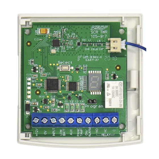
Pulse mode InhIBIt InPut The Inhibit Input can be used with an output +12V 12vDC supply from from a control panel to synchronise the relay the control panel and the On/Off (Arm/Disarm) buttons of a radio key to the state of the control panel. Input INHIBIT INPUT Suitable for arming/disarming control panels From an output on BAtt (such as older Ness panels) which: the control panel a) Require a Pulse (momentary) activation to which is high when pAnIC disarmed and low arm and disarm. tAMp when armed. b) Have an output which is low when the panel ALARM is armed. The Inhibit Input is only active when the relay is set for Pulse mode for On/Off signals. To the control panel keyswitch input. - Page 4 ComPonents Pigtail ANTENNA (Do not cut or extend) SELECT button for Select programming 7 Segment LED DISPLAY PROGRAM PINS Fit the link to enter Program program mode Screw TERMINALS Inputs/Outputs RELAY led dIsPlay oPeRatIon – oPeRatIng mode DISPLAY TOP DOT BOTTOM MEANING Alternating flashing dots IN OPERATING MODE No devices are enrolled. Flashing IN OPERATING MODE One or more devices are enrolled. Flashing IN OPERATING MODE Device number of the last received transmission, with a digit followed by the signal strength of that device, see below. displayed Flashing IN OPERATING MODE Signal strength of the last received transmission on a with a digit scale of 1 (lowest) to 9 (best signal).
-
Page 5: Hold Mode
In Operating Mode, press and hold the SELECT button. The upper left dot will turn on. Then send a signal from a programmed device. The device number and signal strength will display repeatedly allowing you time to check the display. The held signal Strength will continue to cycle until either a new device signal is received or you cancel Hold Mode by a short press of the Select button. Hold Mode will time out after 30 minutes. Restart by press and hold of the SELECT button. STEP-BY-STEP Device Signal Number Strength LONG PRESS Program Select Operating Mode. Display shows Send a signal from The display will show upper left dot. a programmed the device number device. followed by the signal strength - repeating. oPeRatIon tWo Way RadIo FeedBaCk Rather than only sending a signal in one direction, Ness Two Way Radio devices are 'transceivers' and receive a feedback signal from the receiver, giving the true state of the receiver's output. A bi-colour LED on the device provides feedback on the state of the relay on the SCR-TWR receiver after a signal is sent. Example After button press... 106-270 TWR Radio Key RED LED The relay is energised GREEN LED The relay is off... -
Page 6: Operating Mode
PRogRammIng PROGRAM MODE OPERATING MODE Link is ON Link if OFF or 'parked' on one pin Program Program TO ENTER PROGRAM MODE • To enter program mode place the link on the Program pins. • To exit program mode remove the link. Park the link on one pin to prevent losing it. • The relay and the soft outputs are disabled during program mode to prevent unwanted activation. AUTOMATIC EXIT • If the program link is left ON, the device automatically returns to normal operating mode after 5 minutes of no activity of the SELECT button. A brief press of the SELECT button will restart program mode. - Page 7 PRogRammIng menu navIgatoR Programming and setup is easy using the SELECT button and 7 segment LED display. Every action is performed either with a PRESS Single Press Select single press or long press (press and hold) of the Select button. Press and Hold LONG PRESS Select enrol new Program view currently enrolled devices devices the relay delete individual devices or delete all devices Enrol RELAY Device 1 Device 2 Up to Erase all Devices MENU is enrolled is enrolled Device 20 devices Menu...
-
Page 8: Upper Level Menu
uPPeR level menu The upper level programming menu gives access to: • Enrolling new devices • viewing and deleting enrolled devices • Access to the relay menu avaIlaBle oPtIons Enrol RELAY Device 1 Device 2 Up to Erase all Devices MENU is enrolled is enrolled Device 20 devices Menu steP-By-steP STEP DESCRIPTION ACTION DISPLAY NOTE To enter program mode place When 'n' is displayed press the link on the Program pins. and hold SELECT to enter Program the device enrolment mode, see step E1. Press SELECT once. Relay Settings menu, see PRESS step R1, also see the Menu Navigator, page 7. Press SELECT once. -
Page 9: Product Notes
Program Press and hold SELECT. Flashing dash indicates that the LONG PRESS next empty slot is ready to enrol a new device Enrol a new device tWR Radio key: Press ARM & DISARM buttons together other devices: Insert the battery to send a learn signal The device has been enrolled The display shows the slot number of the new device. To enrol another device, press 'n' is displayed PRESS SELECT twice to return to Repeat from step E2 Flashing dash indicates that the LONG PRESS next empty slot is ready to enrol a new device PRoduCt notes 106-267 tWR Reed switch operation with this receiver The TWR Reed Switch has 2 x hardwired inputs as well as a reed switch onboard. When used with the SCR-TWR receiver the reed switch will transmit either the reed switch alarm or the hardwired inputs but not both. • If you are using the hardwired inputs the magnet must be away from the device, therefore only the hardwired inputs are active. • If you are using the onboard reed switch, the hardwired inputs will be ignored. - Page 10 PRogRammIng Relay menu steP-By-steP Program the RELAY TYPE and RELAY OUTPUT CONTROL STEP DESCRIPTION ACTION DISPLAY NOTE To enter program mode place the link on the Program pins. Program RELAY MENU PRESS Press SELECT to display Program the Relay tyPe RELAY TYPE MENU LONG PRESS When is displayed, press and hold SELECT. The currently programmed LONG PRESS When is displayed, press option in the RELAY TYPE and hold SELECT. MENU is displayed Repeatedly pressing SELECT will cycle through the available options in the RELAY TYPE MENU, being Pulse Toggle Latch Exit Choose the required option The saved option will flash LONG PRESS twice then the display then press and hold SELECT...
- Page 11 PRogRammIng deletIng one devICe or deletIng all devICes steP-By-steP STEP DESCRIPTION ACTION DISPLAY NOTE To enter program mode place the link on the Program pins. Program PRESS Press SELECT to skip deletIng one devICe Press SELECT repeatedly to display the enrolled devices Select Select in turn. For example to delete device PRESS 3, press SELECT until is displayed. Then press and hold SELECT LONG PRESS to display Then press and hold SELECT Back to the upper level LONG PRESS menu. to delete the device. deletIng all devICes To abort deleting all devices, PRESS...
-
Page 12: Specifications
OPEN COLLECTOR OUTPUTS Open Collector 100mA @ 12v (low on alarm) LOW BATT, AUX, PANIC/TAMP , ON/OFF RADIO FREQUENCY 902-928 MHz spread spectrum frequency-hopping COMPATIBILITY Ness TWR devices MAX. RADIO DEvICES 20 x TWR devices DIMENSIONS IN HOUSING 75 x 80 x28mm WEIGHT Compatibility (Devices sold separately) 106-270 4 Button Radio Key TWR 106-271 Lux radio PIR TWR 106-272 Micro Radio Reed TWR K-106-267 3 Zone Sensor TWR 106-273 Slim Line Radio Reed TWR Ness Corporation manufacturing processes are accredited to ISO9001 quality standards and all possible care and diligence has been applied during manufacture to ensure the reliable operation of this product. However there are various external factors that may impede or restrict the operation of this product in accordance with the product’s specification. These factors include, but are not limited to: 1. Erratic or reduced radio range. Ness radio products are sophisticated low power devices, however the presence of in-band radio signals, high power transmissions or interference caused by electrical appliances such as wireless routers, cordless phones, computers, Tvs and other electronic devices may reduce the range performance. While such occurrences are unusual, they are possible. In this case it may be necessary to either increase the physical separation between the Ness receiver and other devices or if possible change the radio frequency or channel of the other devices. 2. Unauthorised tampering, physical damage, electrical interruptions such as mains failure, electrical spikes or lightning. Ness SCR-TWR TWO WAY RADIO RECEIvER Installation Notes Rev 1.0 June 2020 Document part number 890-487 www.nesscorporation.com For the products: 106-304 SCR-TWR Receiver National Customer Service Centre Ph: 1300 551 991 © Ness Corporation Pty Ltd ABN 28 069 984 372 Specifications may change without notice.
Need help?
Do you have a question about the SCR-TWR and is the answer not in the manual?
Questions and answers