Advertisement
Quick Links
WL S S E R IE S L A ZY S US A NS
24" - 32" K IDNE Y
INS T A L L A T ION INS T R UC T IONS
14-11/16"
DIMEMSIONS ARE
2-11/16"
23-1/16"
DIMEMSIONS ARE
6-13/16"
FIGURE 1
NOTE: The dimensions shown in Figure 1. are minimum.
1. Insert shelf support in tray from bottom with keyway to rear of tray and position top shelf hub on top of
tray with keyway to rear of tray. Install three (3) 3/4" x #8 (M1812-251-2) self tapping pan head screws
through top hub into shelf support and tighten.
2. Locate the mounting holes with the template (see reverse side) and afix the bottom positioner to the
cabinet floor with four (4) 3/4" x #8 (F1208-13-2) oval head screws. NOTE: Shaft locking screw must
face cabinet opening.
3. Locate the mounting holes with the template and afix the upper pivot support to the underside of the
cabinet top (see Figure 2) with four (4) 1/2" x #8 (F0808-26-2) oval head screws.
4. Working from bottom up, slide the upper shelf onto the shaft. Slide the upper positioner onto the shaft and
temporarily tighten the screw with the positioner approximately 15" from the bottom of the shaft. Slide the
bottom shelf onto the shaft.
5. Insert the upper shaft assembly into the top end of the shaft. Loosely install the lock screw. Insert the
shaft/tray assembly into the bottom positioner. Extend the upper shaft assembly to engage the upper
pivot support (See Figure 2).
6. Adjust the upper shelf position by grasping and supporting the upper shelf positioner assembly while
loosening the locking screw. Rotate the positioner and shelf into alignment and securely tighten the
locking screw.
24"
"MINIMUM"
14-15/16"
19-5/16"
28"
DIMEMSIONS ARE
"MINIMUM"
5-1/16"
32"
"MINIMUM"
21-1/8"
http://www.kitchensource.com/lazy-susan/rv-4wls472-24-52.htm
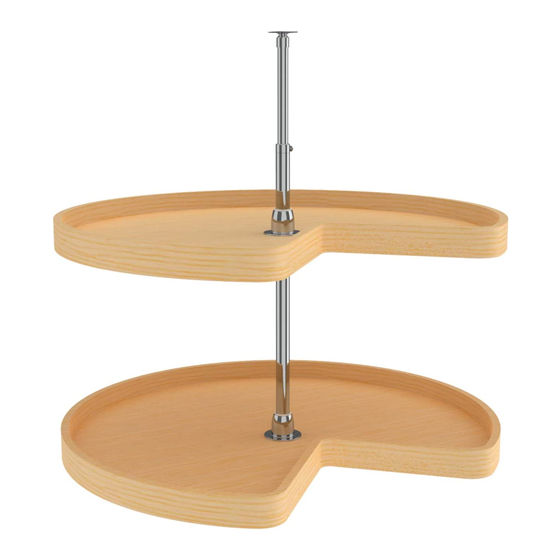
UPPER SHAFT ASSEMBLY
(6470-93-0904-26)
UPPER POSITIONER
(6260-95-2)
SHAFT LOCKING SCREW
(M2408-409-2)
17-11/16"
UPPER PIVOT SUPPORT
(6000-91-2)
LOCKING SCREW
(M2405-409-2)
SHAFT LOCKING SCREW
(M2408-409-2)
SHAFT
(6470-96-2208-26)
SHELF SUPPORT
(6470-07-2)
BOTTOM POSITIONER
(6260-95-2)
FIGURE 2
Advertisement

Related Manuals for Rev-A-Shelf WLS Series


Summary of Contents for Rev-A-Shelf WLS Series
- Page 1 http://www.kitchensource.com/lazy-susan/rv-4wls472-24-52.htm WL S S E R IE S L A ZY S US A NS 24" - 32" K IDNE Y INS T A L L A T ION INS T R UC T IONS UPPER PIVOT SUPPORT (6000-91-2) 14-11/16" UPPER SHAFT ASSEMBLY 24"...
- Page 2 24" , 28" , & 32" K idney NOTES: W L S S eries 1. Be sure to check for adequate clearance at back of shelf prior to drilling holes Ins tallation T emplate 2. Template position may be adjusted for a full overlay door.
Need help?
Do you have a question about the WLS Series and is the answer not in the manual?
Questions and answers