
Related Manuals for Vanderbilt ACTpro MIFARE Classic MF1030e


Summary of Contents for Vanderbilt ACTpro MIFARE Classic MF1030e
- Page 1 ACTpro MIFARE Readers Installation Guide Document ID: A-100500-b Edition date: 02.08.2018...
- Page 2 MIFARE and MIFARE Classic are trademarks of NXP B.V. Hereby, Vanderbilt International (IRL) Ltd declares that this equipment type is in compliance with the following EU Directives for CE marking: • Directive 2014/30/EU (Electromagnetic Compatibility Directive) •...
-
Page 3: Table Of Contents
2.1.1 Panel mount reader connections to the ACTpro door controllers and door stations 2.1.2 LED control 2.1.3 Wiring for Clock & Data / Wiegand reader 2.2 MF1040e/MF1050e 2.2.1 Surface mount 2.2.2 Flush mount 2.2.3 Flush mount to UK pattress box 2.3 MF1030e © Vanderbilt 2018 A-100500-b 02.08.2018... -
Page 4: Overview
MF1050e ACTpro MIFARE Reader with keypad 1.1 Product description ACTpro MIFARE Classic® readers support all Vanderbilt MIFARE cards and fobs. They can be configured to read serial, reverse serial or sector data from any third party MIFARE Classic card. Compatible with Vanderbilt MIFARE cards and fobs... -
Page 5: Reader Connections
ACTpro MIFARE readers must be powered from a fused AC/DC PSU (12–24V, 1A maximum). If the reader is used in a manner not specified in this document, the protection provided by the reader may be impaired. 1.3 Reader connections 1.3.1 MF1040e/MF1050e Sector/Serial operation jumper © Vanderbilt 2018 A-100500-b 02.08.2018... -
Page 6: Mf1030E
The following is the suggested colour coding if using CAT5 or CAT6 cabling. Reader Output Colour Sense White/Green Clock / D1 Green Data / D0 Blue +12V Orange (0V) GND White/Orange Red LED Brown Green LED White/Brown Orange & Purple Programming Sector/Serial Grey (Unused) © Vanderbilt 2018 A-100500-b 02.08.2018... -
Page 7: Wiring For Actpro And Act365
Wind the reader connection cable around the ferrite bead twice tightly. 1.4.2 Clock & Data entry reader Buzzer input (not available on MF1030e) +12V (Red) SENSE (White) 0V / GND (Black) CLOCK / D1 (Green) RED (Brown) DATA / D0 (Blue) GREEN (Yellow) © Vanderbilt 2018 A-100500-b 02.08.2018... -
Page 8: Clock & Data Exit Reader
IMPORTANT: To put ACTpro MIFARE readers into Wiegand, mode connect the SENSE on the reader to 0V/GND. Buzzer input (not available on MF1030e) +12V (Red) SENSE 0V / GND (Black, White) CLOCK / D1 (Green) RED (Brown) DATA / D0 (Blue) GREEN (Yellow) © Vanderbilt 2018 A-100500-b 02.08.2018... -
Page 9: Wiegand Exit Reader
The default sector reader operation reads a number encoded into Sector 1 of the MIFARE cards and fobs. The ACTpro MIFARE readers can be programmed to read any specified sector data. See Reader re- programming on the facing page. © Vanderbilt 2018 A-100500-b 02.08.2018... -
Page 10: Serial And Reverse Serial Reader
ACTpro MIFARE readers that have been programmed to read third-party MIFARE cards and fobs will play a series of ascending notes after being powered up in addition to the standard beep codes, this is to indicate that it no longer reads the MIFARE cards and fobs issued by Vanderbilt. 1.6.1 Backlight operation – MF1050e The MF1050e ACTpro MIFARE Reader has backlight illumination of the keypad. - Page 11 Note: If the reader has been re-programmed (see Reader re-programming on the previous page), then a series of notes is played after the second beep set, this indicates that the default programming to read ACTpro MIFARE cards has been changed. © Vanderbilt 2018 A-100500-b 02.08.2018...
-
Page 12: Mounting Instructions
4. Use the wiring diagram below to connect the reader to the controller. 5. When wiring is complete, place the front cover back onto the audio entry panel. 6. Apply power to the controller and test the reader with a card or fob. © Vanderbilt 2018 A-100500-b 02.08.2018... -
Page 13: Panel Mount Reader Connections To The Actpro Door Controllers And Door Stations
Readers should be a maximum of 100m apart when powered from +12V. White SENSE Green CLOCK & DATA 1 Blue DATA / DATA 0 +12V Black Brown RED LED Yellow GREEN LED Orange BUZZER Ctrl © Vanderbilt 2018 A-100500-b 02.08.2018... -
Page 14: Mf1040E/Mf1050E
Prepare the mounting surface to receive sub-surface terminals. Mount the flush mount collar on the wall using the fixing kit supplied in the box. Place the reader/keypad onto the surface mount collar and clip down into place. © Vanderbilt 2018 A-100500-b 02.08.2018... -
Page 15: Flush Mount To Uk Pattress Box
D Place the reader/keypad onto the surface mount collar and clip down into place. Use the security screw supplied to attached the unit to the flush mount collar. Place the cap onto the unit and push firmly in place. © Vanderbilt 2018 A-100500-b 02.08.2018... -
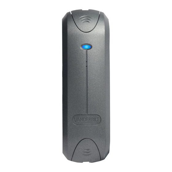
Page 16: Mf1030E
ACTpro MIFARE Readers – Installation Guide Mounting instructions 2.3 MF1030e Screw unit to the surface. Place caps on to the unit and push firmly into place. © Vanderbilt 2018 A-100500-b 02.08.2018... - Page 17 © Vanderbilt 2018 Data and design subject to change without notice. Supply subject to availability. Document ID: A-100500-b Edition date: 02.08.2018 Issued by Vanderbilt International Ltd. Clonshaugh Business and Technology Park vanderbiltindustries.com Clonshaugh, Dublin D17 KV 84, Ireland @VanderbiltInd Vanderbilt Industries...
Need help?
Do you have a question about the ACTpro MIFARE Classic MF1030e and is the answer not in the manual?
Questions and answers