Table of Contents
Advertisement
Quick Links
729100419
Owner's Manual
& Assembly Guide
Gloves must be worn
at all times to reduce
risk of injury!
1-800-851-1085
assist@arrowsheds.com
BUILDING DIMENSIONS
†
Approx.
Storage
Size
Area
12' x 10'
116 Sq. Ft. 1043 Cu. Ft.
2
3,7 m x 3,0 m
10,8 m
Each Extension adds an additional 60" (152,4 cm) in length, 59 Sq. Ft. (5,4
additional storage area, and 529 Cu. Ft. (15,0
or
†
Size rounded off to the nearest foot
Exterior Dimensions
(Roof Edge to Roof Edge)
Width
Depth
146.13"
123.56"
3
29,5 m
371,2cm
313,8 cm
m 3
) additional storage volume.
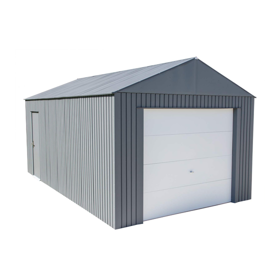
EVEREST SERIES
Size
Additional
per Extension
Interior Dimensions
Height
Width
Depth
123.48"
141.13"
118.30"
313,6 cm
358,5 cm
300,5 cm
2
)
m
12' GARAGE
142.13" x 119.25"
361,0 cm x 302,9 cm
142.13" x 60"
361,0 cm x 152,4 cm
Door
Opening
Height
Width
122.23"
28.30"
(Roll Up Door)
95.00"
310,5 cm
71,9 cm 199,0 cm
(Roll Up Door)
241,3 cm 212,5 cm
* See Inside for Detailed Safety Information.
01GW
All Sizes
Height
78.35"
83.66"
Advertisement
Table of Contents

Subscribe to Our Youtube Channel
Related Manuals for Sojag EVEREST Series


Summary of Contents for Sojag EVEREST Series
- Page 1 01GW 729100419 Owner’s Manual & Assembly Guide EVEREST SERIES Gloves must be worn at all times to reduce All Sizes 12’ GARAGE risk of injury! Customer Service: Base 142.13” x 119.25” 1-800-851-1085 Size 361,0 cm x 302,9 cm assist@arrowsheds.com Additional 142.13”...
- Page 2 GB: Assembly manual in additional languages available online. Scan QR code below to access. FR: Manuel de montage disponible en ligne dans d’autres langues. Pour y accéder, scannez le code QR ci-dessous. DE: Montageanleitung in zusätzlichen Sprachen online verfügbar. Scannen Sie den QR-Code unten, um darauf zuzugreifen. IT: Manuale dell’assemblea in altre lingue disponibile online.
- Page 3 03GW SAFETY & MAINTENANCE Safety precautions MUST be followed at all times throughout the construction of your building! Care must be taken when handling Practice caution with the tools being Do NOT attempt to assemble your various pieces of your building since used in the assembly of this building.
- Page 4 07BQ ASSEMBLY TIPS & TOOLS Watch the Weather Closely: Be sure the day you choose to install your building is dry and calm. Do NOT attempt to assemble your building on a windy day. Be careful on wet or muddy ground. Use Teamwork: Two or more people are required to assemble your building.
- Page 5 05GW Base The Base For Your Building Concrete Slab The slab should be at least 4" (10,2 cm) thick. It must be level and fl at to provide good support for the frame. The following are the recommended materials for your base. 2 x 4's (38 mm x 89 mm) (will be removed once the concrete cures) Concrete Sheet of 6 mil plastic...
- Page 6 06GW Anchoring Anchoring Down The Building It is important that the entire fl oor frame be anchored after the building is erected. Below are recommended ways of anchoring. Anchoring into Concrete: Anchoring into Wood: Use 1/4" (6 mm) Wood Screws. There are 1/4" (6 mm) For poured concrete slab or footing or patio blocks: Use 1/4"...
- Page 7 07GW HARDWARE LIST... Part Part Hardware Views by Key No. Qty. Description List 65103 Hex Nut (#8-32) 65101 Square Nut (1/4-20) 65106 Square Nut (#10-32) 4, 5, 6 8, 9, 10 65943 Bolt (Bare) (#10-32 x 7/16) (10 mm) 65943 Bolt (Wall Color) (#10-32 x 7/16) (10 mm) 65943 Bolt (Roof Color) (#10-32 x 7/16) (10 mm)
- Page 8 08GW PARTS LIST... Confi rm that all hardware and parts are present before attempting to assemble your Storage Unit. For missing or damaged parts contact Customer Service. Do not return to store. Customer Service: 1-800-851-1085 or assist@arrowsheds.com Assembly Part Part Extension Key No.
- Page 9 09GW PARTS LIST... Assembly Part Part Extension Key No. Number Description 1205M Frame, Rear Right 11180 Header Angle Side 11181 Panel, Jamb Right 11182 Track Strut 11183 Frame, Side 11184 Panel, Jamb Right 11185 11186 Truss, Column 11187 Chord, Truss Upper 11188 Chord, Truss Lower 11189...
- Page 10 10GW Components for Garage Door (GD) #3 End Hinge #2 End Hinge #1 End Hinge #1 Center Hinge Door Section with Door Section weather stripping Roller Inside Step Plate Door Lock Assembly Bottom Bottom Fixture Left Fixture Fixture Right...
- Page 11 11GW Components for Garage Door (GD) Snap Latch Snap Latch Keeper Cable Vertical Track Flag Angle Flag Angle Left Right Horizontal Curve Horizontal Curve Track Right Track Left Track Bracket Safety Spring Extension Spring Cable Cable Cable Clip Pulley S Hook Cable Clip Clevis...
- Page 12 12GW Hardware for Garage Door (GD) 1/4” Sheet 10-24 x 5/8” Hex Bolt with Metal Screw Bolt Hole 1/4” Self 1/4” Self 1/4” Wiz Nut Drilling Screw Drilling Screw 3/8” x 3/4” Carriage Bolt 3/8” x 1-1/2” Bolt 1/4” x 5/8” Track Bolt &...
- Page 13 13GW ASSEMBLY OVERVIEW...
- Page 14 14GW ASSEMBLY OVERVIEW...
- Page 15 15GW ASSEMBLY OVERVIEW 33 33...
- Page 16 16GW Step 1A 65106 11162 80159 11150 65943 (x12) (x2) (x2) (x2) (x12) Washers are to be used on painted parts only. Washers are not necessary on unpainted parts and there are not enough to use on every screw and bolt. 11162 11162 11162...
- Page 17 17GW Step 1B 65106 11292 80141 65943 Rear (x1) (x1) (x1) (x1) Door Rear Option A Extension Door Option A 12x10 Door 12x15 Door Option B Option B Front Front For Door Option A, put the ramp on the left rear frame. For Door Option B, put the ramp on the right front frame.
- Page 18 18GW Step 1C 11151 80141 80145 11158 (x2) (x1) (x1) (x1) 65106 Rear 65943 *Bend tabs up for 80141 and 11151 (x8) (x8) *Holes on Outside Door Option A 12x10 Door Option B Front *Holes on Outside 11’ 9-1/8” 358,5 cm 11151 Rear From Step 1A...
- Page 19 19GW Step 2A 12x10 x1 Extension x1 66611 11188 11190 11189 11192 (x40) (x2) (x1) (x2) (x2) *Lubricate screws to aid assembly 11192 11192 11190 11190 11190 11190 11188 11188 11189 11’ 3-3/4” (344,8 cm) Washers are to be used on painted parts only.
- Page 20 20GW Step 2B 11191 11187 66611 (x2) (x2) (x36) *Lubricate screws to aid assembly 11191 11191 11191 11187 11192 11192 11190 11191 11191 11187 11187 11187 11188...
- Page 21 21GW Step 2C 65106 65943 7003 7004 (x2) (x2) (x6) (x6) 66611 (x24) 7003 7004 *Lubricate screws to aid assembly Hand tighten bolt 7004 7003 7004 7003 7004 7003 7004 7003...
- Page 22 22GW Step 2D 6228 66611 11186 (x2) (x20) (x2) *Lubricate screws 7022 to aid assembly 11187 7022 7022 11186 (x4) 11186 11186 Tab end to center of building 6228 11189 6228 11’ 9-1/8” (358,5 cm)
- Page 23 23GW Step 3A 12x10 12x15+ 66611 Skip to Step 6A Continue on pg 29 Next Page (x4) *Lubricate screws to aid assembly Rear Front...
- Page 24 24GW Step 3B 12x15+ Only 66611 11159 11163 11155 (x2) (x16) (x2) (x2) *Lubricate screws to aid assembly 65106 65943 (x4) (x4) *Bend tabs up for 11163 and 11155 11159 11159 11159 *Holes on Outside 11163 11159 11163 11163 11155 11155 11155 *Holes on Outside...
- Page 25 25GW Step 3C 12x15+ Only 66611 11177 (x4) (x2) *Lubricate screws to aid assembly *11177 is for temporary use in this step and is used in a later step 11177 11177...
- Page 26 26GW Step 4A 12x15+ Only 65106 65943 Make a double roof (x22) (x22) beam assembly 11154 (x6) *Remove bolt linking brackets before installing roof beams Double beam assembly Front View Single roof beam 11154 11154 11154 11154 11154...
- Page 27 27GW Step 4B 12x15+ Only 65106 6372 65943 (x6) (x6) (x2) 6372 6372...
- Page 28 28GW Step 5 12x20 *12x25+ 11157 11157 11157 11157 *For buildings 25’ and longer, attach 2 wall panels as shown every 10’ for support. Follow Step 12A on page 48 for screw placement...
- Page 29 29GW Step 6A 12x10+ Continued Continue supporting truss for 12x10 until frame is complete 66611 (x4) *Lubricate screws to aid assembly From Step 1C Front From Step 1C...
- Page 30 30GW Step 6B 66611 11156 11165 (x1) (x1) (x4) *Lubricate screws to aid assembly *Holes on Outside 11165 11156 11165 11156 Front...
- Page 31 31GW Step 6C 65106 11152 11156 65943 (x1) (x1) (x1) (x1) 66611 (x2) *Holes on Outside 11152 11152 11152 11152 11156 11156 11165 11156 11156 Front...
- Page 32 32GW Step 6D 80143 11156 80147 65106 65943 (x1) (x1) (x1) (x2) (x1) Repeat Steps 6B and 6C 66611 for the other side with holes facing outside 80143 For Door Option B, (x6) follow Step 9 on page 39 in place of this step 11156 80147 11156...
- Page 33 33GW Step 6E 11158 80145 66611 (x2) (x2) (x8) 65106 65943 (x6) (x6) *Holes on Outside *Holes on Outside 80145 11158 80145 11158 Front...
- Page 34 34GW Step 7A *Leave outside top bolt 65106 11179 out for both columns 65943 (x10) (x2) (x10) 11179 11179 Front...
- Page 35 35GW Step 7B 65106 80191 11290 65943 (x10) (x10) (x1) (x1) 80191 11290 11290 80191 Front...
- Page 36 36GW Step 7C 65106 65943 (x8) (x8) 11201 11161 11201 11161 (x2) (x1) 11161 11161 11201 11161 From Step 1A Front...
- Page 37 37GW Step 8A 66611 11156 11165 (x4) (x1) (x1) *Lubricate screws to aid assembly *Holes on Outside 11165 11156 11165 11156 Rear...
- Page 38 38GW Step 8B 65106 66611 65943 11152 11156 (x1) (x1) (x2) (x1) (x1) *Holes on Outside 11152 11152 11152 11152 11156 11156 11165 11156 11156 Rear...
- Page 39 39GW Step 9 11184 11176 65106 66611 65943 (x1) (x1) (x1) (x1) (x9) 80143 11156 80143 (x1) (x2) For Door Option B, follow Step 6D on page 32 in place of this step Rear 11156 Door Option A 12x10 Door Option B 11176 Truss...
- Page 40 40GW Step 10A 11186 66611 (x8) (x1) *Lubricate screws to aid assembly From Step 1A 11186 Rear...
- Page 41 41GW Step 10B 66611 65106 65943 11180 80149 (x5) (x6) (x1) (x1) (x5) *Lubricate screws *Bend tabs up for 80149 and 11180 to aid assembly 80149 11180 Rear...
- Page 42 42GW Step 11A 7943 6381 6380 7942 (x2) (x4) (x2) (x4) 65106 65943 66646 (x28) (x28) (x28) 6381 *Bolts to match wall panel color 6381 Mounting leg faces inwards Mounting leg faces inwards 7943 7942 6380 6380 Mounting leg faces inwards...
- Page 43 43GW Step 11B 66611 6382 65106 65943 6382 (x40) (x6) (x2) (x6) Front Rear...
- Page 44 44GW Step 11C *Repeat this page for the Rear of the shed Make 2 double roof 11149 beam assemblies 65106 65943 (x12) (x44) (x44) Top View Gable Beam Double beam assembly Single roof beam *Remove bolt linking brackets before installing roof beams Double beam assembly Front View...
- Page 45 45GW Step 11D 6372 65106 65943 (x14) (x4) (x14) 6372 6372 Rear Front 6372 6372...
- Page 46 46GW OPTIONAL CAULK APPLICATION To reduce water infi ltration, apply caulk around the perimeter of the shed before installing panels.
- Page 47 47GW Side Panel Orientation 11157 11157 11157 11157 12x10 Rear Front Door 11160 11157 11157 Option A 12x15 11157 11166 11157 11157 11157 11157 11157 Extension Kit(s) Rear Front Extension Kit(s) Door 11157 11157 11157 11157 11166 11160 Option A...
- Page 48 48GW Step 12A 66611 11157 Extension x1 *For 12x15’+ sheds, 66646 remove the bracing 66611 11157 from step 3C on page 66646 (x3) 25. Set that piece (x48) (x48) aside for later use. *Lubricate screws (x4) (x66) (x66) to aid assembly Washers are to be used on painted parts only.
- Page 49 49GW Step 12B 66611 11157 66646 (x54) (x3) (x54) Painted screws are to be used on painted parts only. Make sure painted screws match wall color. *When overlapping panels, make sure arrow is towards the top and covered up Continue installing panels up to each of the corners except by the door.
- Page 50 50GW Step 12C 12x15+ Only 66611 11166 66646 (x24) (x2) (x24) Painted screws are to be used on painted parts only. Make sure painted screws match wall color. Install Panels to cover each of the gaps except around door 11166 *When overlapping panels, make sure arrow is towards the top and covered up...
- Page 51 51GW Step 13A 66611 11181 11207 65106 65943 66646 (x4) (x1) (x1) (x4) (x1) (x1) 11181 *When overlapping panels, make sure arrow is towards the top and covered up Door Option A shown 11181 11181 11181 Painted screws are to be used on painted parts only. Make sure painted screws match wall color.
- Page 52 52GW Step 13B 66611 65106 65943 66646 (x7) (x7) (x7) (x14) 11291 11170 *When overlapping panels, make sure (x1) (x1) arrow is towards the top and covered up Painted fasteners are to be used on painted parts only. Make sure painted fasteners match wall color. 11170 11291 11170...
- Page 53 53GW Step 13C 66611 11160 65106 65943 66646 (x7) (x1) (x1) (x8) (x1) Painted fasteners are to be used on painted parts only. Make sure painted fasteners match wall color. *When overlapping panels, make sure arrow is towards the top and covered up 11160...
- Page 54 54GW Step 13D 66611 11182 80153 (x1) (x1) (x10) 66646 (x10) 11182 80153...
- Page 55 55GW Step 14 80161 11173 11169 11172 66611 66646 (x1) (x1) (x1) (x68) (x4) (x68) Painted fasteners are to be used on painted parts only. Make sure painted fasteners match wall color. 11172 11172 11169 11173 11172 11172 80161 *When overlapping panels, make sure arrow is covered up...
- Page 56 56GW Step 15 11166 11157 66611 66646 (x3) (x4) (x96) (x96) Painted fasteners are to be used on painted parts only. Make sure painted fasteners match wall color. *When overlapping panels, make sure arrow is towards the top and covered up *Panels don’t go all the way to corner 11166 11157...
- Page 57 57GW Step 16A 11168 11153 (x4) (x4) 65106 65943 66646 11168 (x28) 11153 (x28) (x28) Painted fasteners are to be used on painted parts only. Make sure painted fasteners match wall color.
- Page 58 58GW Step 16B Painted fasteners are to be used on painted parts 66611 66646 only. Make sure painted fasteners match wall color. (x48) (x48) Install the corner panel subassemblies to each of the 4 corners. Front Subassembly Subassembly from page 57 from page 57 Rear...
- Page 59 59GW Roof Panel Orientation Rear 80151 11178 12x10 11174 11174 11174 11174 11174 11174 11174 11174 80151 11178 Front Rear 80151 11178 12x15 11174 11174 11174 11174 11174 11174 Extension Kit(s) 11174 11174 11175 11175 11174 11174 11174 11174 11178 80151 Front...
- Page 60 60GW Step 17A 66611 65106 65943 11178 66646 (x5) (x5) (x8) (x13) (x1) Use painted fasteners that match roof panel color 11178 Front...
- Page 61 61GW Step 17B 66611 11174 66646 (x48) (x2) (x48) Use painted fasteners that match roof panel color *When overlapping panels, make sure arrow is towards the top and covered up 11174 11174 Front...
- Page 62 62GW Step 17C Extension x1 12x15+ 66611 11174 11175 65106 66646 65943 (x2) (x60) (x59) (x1) (x1) (x1) *Lubricate screws to aid assembly Use painted fasteners that match roof panel color *When overlapping panels, make sure arrow is towards the top and covered up Install panels in this order for every 5’...
- Page 63 63GW Step 17D 66611 80151 11174 65106 66646 65943 (x65) (x2) (x1) (x6) (x59) (x6) Use painted fasteners that match roof panel color *When overlapping panels, make sure arrow is towards the top and covered up *Use bolt for top of truss Rear 80151 11174...
- Page 64 64GW Step 18A 66611 11178 11174 11202 66646 65106 65943 (x2) (x65) (x1) (x1) (x56) (x11) (x11) 30003 (x1) Use painted fasteners that match roof panel color *When overlapping panels, make sure arrow is towards the top and covered up Rear 11178 11174...
- Page 65 65GW Step 18B Extension x1 65106 11174 11205 66611 65943 12x15+ 66646 (x7) (x54) (x2) (x1) (x7) (x47) *Lubricate screws Use painted fasteners that match roof panel color to aid assembly *Use bolt for top of truss Rear 11174 11174 *When overlapping panels, make sure arrow is towards the top and covered up 11205...
- Page 66 66GW Step 18C Extension x1 12x15+ 66611 11175 65106 65943 66646 (x14) (x2) (x1) (x2) (x12) Use painted fasteners that match roof panel color *When overlapping panels, make sure arrow is towards the top and covered up 11175...
- Page 67 67GW Step 18D 66611 65106 11174 66646 11202 65943 (x54) (x7) (x2) (x47) (x7) (x1) *Lubricate screws Use painted fasteners that match roof panel color to aid assembly *Use bolt for top of truss 11174 11174 Front *When overlapping panels, make sure arrow is towards the top and covered up 11202...
- Page 68 68GW Step 18E 66611 65106 80151 30003 65943 66646 (x7) (x17) (x12) (x7) (x1) (x1) Use painted fasteners that match roof panel color *When overlapping panels, make sure arrow is towards the top and covered up 80151 Front 30003...
- Page 69 69GW Step 19 Extension x1 66611 11204 66646 66611 11203 66646 (x4) (x10) (x14) (x4) (x8) (x2) (x8) Install roof trim on both sides of the shed Front 11204 11203 12x15+ Install a 11203 roof trim for every 5’ extension section Rear 11204...
- Page 70 70GW Step 20A 66611 11200 11195 (x1) (x2) (x6) 11195 11195 11200...
- Page 71 71GW Step 20B 30005 30018 Once tape sticks to a surface it CAN NOT be removed. (x1) (x2) Wipe the legs of 11195 thoroughly with alcohol pads (30018) before applying tape (30005) Approximately 11” (27,9 cm) Approximately 11” (27,9 cm) Press tape fi...
- Page 72 72GW Step 20C 66783 65103 66609 11193 (x3) (x1) (x9) (x9) 11193 66609...
- Page 73 73GW Step 20D M5x10 Screw M5 Hex Nut Mortise Use hardware supplied M5 Washer with handle assembly box for this page (x2) (x1) (x2) (x2) Make sure holes are in the orientation shown Mortise Door Latch Orientation Top View Outside Door Outside Door Correct Incorrect...
- Page 74 74GW Step 20E Peel off the backs of the tape before proceeding. Once tape sticks to a surface it CAN NOT be removed. Lay the front panel on a fl at From Step 20B surface. Using at least 2 people, place the edge of the back panel on the edge of the front panel with the mortise From Step 20D...
- Page 75 75GW Step 20F Use painted fasteners that match wall color 66611 11196 66646 *Washers on outside only (x6) (x2) (x22) 11196 11196...
- Page 76 76GW Step 21A Use hardware supplied with handle assembly box for this page Strike Plate (x1) M5x10 Screw M5 Hex Nut (x2) (x2) 11182 80153...
- Page 77 77GW Step 21B 66611 11177 (x2) (x6) 11177 11177...
- Page 78 78GW Step 21C 66783 65103 (x9) (x9)
- Page 79 79GW Step 22A Use hardware supplied with handle assembly M4x5 Screw box for this page (x2) Post goes in all the way Use Allen wrench to tighten set screw DO NOT lose keys. Replacement keys are not available...
- Page 80 80GW Step 22B Use hardware supplied M5x30 Screw Back Handle with handle assembly box for this page (x2) (x1) Back Handle From Step 22A...
- Page 81 81GW Step 23A: Bottom Panel 1/4” Sheet Metal Inside Step Plate Screw Bottom Door Section Bottom Gripping Point/Step Plate Kit Look for the section with weather seal attached to it. This is the bottom section. Set it on table face down (the face is the outside of the door).
- Page 82 82GW Step 23B: Bottom Panel 1/4” Sheet Metal 1/4” Self Drilling Bottom Fixture Bottom Fixture #1 Center Hinge #1 End Hinge Screw Screw (Red) Roller Right Left Roller Sections are attached to each other with hinges. Fasten Carrier hinges marked #1 to top of bottom section at each stile us- ing (2) 1/4”...
- Page 83 83GW Step 24A: #2 Panel 10-24 x 5/8” #2 Door Section Door Lock Assembly Bolt Drill three 1/2” holes into the section face. Drill completely through the section for the middle hole. Install lock assembly in section. #2 Section lock/outside handle 10-24 x 5/8”...
- Page 84 84GW Step 24B: #2 Panel 1/4” Self Drilling Snap Latch Screw Attach a snap latch assembly to each end stile using two 1/4” self drilling screws. #2 Section 1/4” self drilling screw snap latch 1/4” self drilling screw...
- Page 85 85GW Step 24C: #2 Panel 1/4” Sheet Metal #1 Center Hinge #2 End Hinge Roller Screw Fasten end hinges marked #2 to top of section on each end stile. Use (2) 1/4” sheet metal screws per hinge. Make sure that the two slots are at top of hinge. Insert a roller into each end hinge as shown. Attach #1 center hinge.
- Page 86 86GW Step 25: #3 Panel 1/4” Sheet Metal #1 Center Hinge #3 Door Section #3 End Hinge Roller Screw Fasten end hinges marked #3 to top of section on each end stile. Use (2) 1/4” sheet metal screws per hinge. Make sure that the two slots are at top of hinge. Insert a roller into each end hinge as shown. Attach #1 center hinge.
- Page 87 87GW Step 26A: Track Installation 1/4” x 5/8” Track 5.5 Track 4.5 Track Flag Angle Right Flag Angle Left Bolt & Hex Nut Bracket Vertical Track Bracket Prepare the Vertical Tracks. The top of the vertical track must pitch back from the jamb for door to seal properly. This spacing is set by use of graduated track brackets.
- Page 88 88GW Step 26B: Track Installation 1/4-20x1/2” Hex 1/4-20 Square 1” Washers Head Bolt Fasten the vertical track and fl ag angle assembly to the door jamb using 1/4” Bolt and Hex Nut with 1” Washer. Follow the orientation as shown below. Do this for both the right and left vertical tracks. 1”...
- Page 89 89GW Step 27A: Insert Panels Assemblies from Step 23: • Bottom Panel Subassembly Insert the bottom section into the doorway. Slide the rollers into the vertical track as shown. Center and level bottom section in opening. If there is a gap on one end at the fl oor then the track will not rest on the fl...
- Page 90 90GW Step 27B: Insert Panels Assemblies from Step 24: • #2 Panel Subassembly Stack #2 section (with #2 end hinges) on top of bottom (#1) section while sliding rollers into vertical track. #2 Panel Assembly Roller Vertical Track...
- Page 91 91GW Step 27C: Insert Panels 1/4” Sheet Metal Screw Attach the #1 end hinges and center hinge to the #2 section with 1/4” sheet metal screws. 1/4” Sheet Metal Screws...
- Page 92 92GW Step 27D: Insert Panels Assemblies from Step 25: • #3 Panel Subassembly Stack #3 section (with #3 end hinges) on top of #2 section while sliding rollers into vertical track. #3 Panel Assembly Roller Vertical Track...
- Page 93 93GW Step 27E: Insert Panels 1/4” Sheet Metal Screw Attach the #2 end hinges and center hinge to the #3 section with 1/4” sheet metal screws. 1/4” Sheet Metal Screws...
- Page 94 94GW Step 28: Snap Latch Keeper 1/4” x 5/8” Track Snap Latch Bolt & Hex Nut Keeper Attach a snap latch keeper to each vertical track using a bolt and nut. right hand vertical track #2 Panel Assembly snap latch keeper 1/4”...
- Page 95 95GW Step 29: Thread Cable Hex Bolt with 1/4” Wiz Nut Cable Hole Insert cable through left snap latch hole. Place left hand a lug on the end of the cable to prevent it from vertical track sliding out. snap latch cable Feed the cable through the inside handle.
- Page 96 96GW Step 30A: Horizontal Track 11197 66611 65106 65943 (x8) (x8) (x4) (x8) Assemble door track supports using screws. 11197 11197 11197 (x2) TOP VIEW 11197 Roof Beam Attach door track support assembly to roof beam using four bolts and square nuts. FRONT...
- Page 97 97GW Step 30B: Horizontal Track 66611 11183 (x4) (x2) 12x10 Attach track strut to rear frame using one screw. VIEW FACING REAR 11183 11183 VIEW FACING FRONT Attach track strut to door track support assembly using one screw.
- Page 98 98GW Step 30C: Horizontal Track 11183 66611 (x4) (x2) Attach track strut to door track support 12x15+ assembly using one screw. Truss Truss FRONT VIEW FACING 11183 FRONT 11183 VIEW FACING REAR Attach track strut to truss using one screw. 11183 11183 Truss...
- Page 99 99GW Step 30D: Horizontal Track 3/8” x 3/4” Carriage 1/4” x 5/8” Track Left Horizontal Right Horizontal Bolt and Hex Nut Bolt & Hex Nut Curve Track Curve Track Have another person hold the end of the Fasten angle (attached to horizontal curve left horizontal curve track.
- Page 100 100GW Step 30E: Horizontal Track 65106 65943 (x4) (x4) Attach the end of the Left Horizontal Curve Track to the Door Track Support Assembly using bolts and nuts as shown. Repeat for Right Horizontal Track. Door Track Support Assembly Left Horizontal Curve Track...
- Page 101 101GW Step 31A: Insert Top Panel Top Door Section Assembling the top door panel will require another person holding the door section while attaching the fi xtures and hinges. Make sure adequate help is available before continuing on with the installation. Have someone stack the top section on top of the other door sections and hold it there.
- Page 102 102GW Step 31B: Insert Top Panel 1/4” Sheet Metal Top Fixture Roller Screw Place a roller inside of a top fi xture. Roller Fixture Slide the roller into the horizontal track where it is wide enough to put the roller as shown. You may have to angle it in. Slide the roller through the track so it lines up with the top track.
- Page 103 103GW Step 31C: Insert Top Panel 1/4” Sheet Metal Top Fixture Roller Screw Section Place another roller into the other top fi xture. Fixture Roller Slide the roller into the horizontal track where it is wide enough to put the roller as shown.
- Page 104 104GW Step 31D: Insert Top Panel 1/4” Sheet Metal Screw Attach the #3 end hinges and center hinge to the top section with 1/4” sheet metal screws. 1/4” Sheet Metal Screws...
- Page 105 105GW Spring Assembly Preparation Check all spring assembly instructions and parts. Warning! If there appears to be any parts missing stop here and contact your Arrow Customer Service im- mediately. Do not substitute parts. Warning! Do not remove any factory applied spring tag or warning label! If any tags or labels are missing or unreadable, contact your Arrow Customer Service immediately.
- Page 106 106GW Step 32A: Extension Spring Assembly 3/8” x 1-1/2” Bolt and Hex Nut Pulley Pulley Attach pulley with a 3/8” x 1-1/2” bolt and hex nut on 3/8” x 1-1/2” angle which attaches horizontal track to fl ag angle. Bolt Repeat this step for opposite side of door.
- Page 107 107GW Step 32B: Extension Spring Assembly 3/8” x 1-1/2” Bolt Eyebolt and Hex Extension Pulley Clevis Safety Cable and Hex Nut Spring Assemble spring as shown. Bolt a clevis and pulley on one end Clevis 3/8” x 1-1/2” Bolt Extension Spring Hex Nut Pulley Warning! Extension springs can cause severe damage, personal injury or even death if they are not properly...
- Page 108 108GW Step 32C: Extension Spring Assembly Spring Cable S Hook Cable Clip Attach spring cable loop to bottom Spring fi xture stud and thread spring cable Cable Loop over pulley. Pulley Thread spring cable around spring pulley. Spring Pulley Spring Cable Bottom Fixture Stud...
- Page 109 109GW Step 32D: Extension Spring Assembly 1/4-20x1/2” Hex 1/4-20 Square Cable Clip Head Bolt Attach cable clip to track support using bolt Safety Cable and nut. Tie the safety cable securely to the cable clip as shown. Cable Clip 1/4” Bolt Cable Knot...
- Page 110 110GW Step 33 66611 11185 11171 66646 (x16) (x1) (x1) (x16) Painted fasteners are to be used on painted parts only. Make sure painted fasteners match wall color. 11185 11171 Front IMPORTANT: It is important that building be anchored after construction. See page 6 for recommended ways of anchoring.
- Page 111 ASSEMBLY NOTES...
- Page 112 ASSEMBLY NOTES...
Need help?
Do you have a question about the EVEREST Series and is the answer not in the manual?
Questions and answers