Sign In
Upload
Download
Table of Contents
Contents
Add to my manuals
Delete from my manuals
Share
URL of this page:
HTML Link:
Bookmark this page
Add
Manual will be automatically added to "My Manuals"
Print this page
×
Bookmark added
×
Added to my manuals
Manuals
Brands
BAC Manuals
Air Conditioner
1500 Series
Rigging & assembly instructions
BAC 1500 Series Rigging & Assembly Instructions
Cooling tower
Hide thumbs
1
2
Table Of Contents
3
4
5
6
7
8
9
10
11
12
13
14
15
16
17
18
19
20
21
22
23
24
25
26
27
28
29
30
page
of
30
Go
/
30
Contents
Table of Contents
Bookmarks
Table of Contents
Table of Contents
Introduction
Safety
Shipping
Pre-Rigging Checks
Unit Weights
Anchoring
Cold Weather Operation
Location
Warranties
Unit Operation
Rigging & Assembly
Rigging
Single-Cell Installation
Two Piece Section Assembly
Multi-Cell Installation
Multi-Cell Unit Assembly
Flume Box Installation
Positive Closure Plate Installation
Motor Location and Conduit Installation
Fan Guard Installation
Optional Accessory Installation
Bottom Water Outlet/Equalizer/Bypasses
Access Door Platform and Ladder
Internal Service Platform
Internal Service Platform Ladder
Internal Ladder Only
External Access Platform
External Access Platform for Multi-Cell Units
Ladder Safety Cage
Louver Face External Access Platform Ladder
Louver Face External Access Platform with End Ladder
Hot Water Basin Handrail for Multi-Cell Units
Hot Water Basin Handrail Ladder
Motor Removal System with Davit Arm
Fan Cowl Extensions
Basin Accessories
Heater Control Panel
Advertisement
Quick Links
1
Table of Contents
2
Introduction
3
Unit Operation
4
Unit Weights
5
Cold Weather Operation
6
Single-Cell Installation
7
Motor Location and Conduit Installation
Download this manual
Series 1500
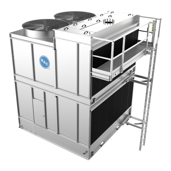
Series 1500 Cooling Tower
RIGGING & ASSEMBLY INSTRUCTIONS
Table of
Contents
Previous
Page
Next
Page
1
2
3
4
5
Advertisement
Table of Contents
Need help?
Do you have a question about the 1500 Series and is the answer not in the manual?
Ask a question
Questions and answers
Related Manuals for BAC 1500 Series
Air Conditioner BAC 3240C Operation & Maintenance Manual
Series 3000 cooling tower (42 pages)
Air Conditioner BAC 3000 Series Operation & Maintenance Manual
Cooling tower (48 pages)
Air Conditioner BAC Trillium Series Rigging, Installation, Operation & Maintenance Manual
Adiabatic products (63 pages)
Air Conditioner BAC VCL Series Operating And Maintenance Instructions Manual
Evaporative condensers (34 pages)
Air Conditioner BAC VCL Operating And Maintenance Instructions Manual
Evaporative condenser (32 pages)
Air Conditioner BAC HXI Series Operating And Maintenance Instructions Manual
Hybrid closed circuit cooling tower (40 pages)
Air Conditioner BAC S1500E Rigging And Installation Instructions
Open cooling tower (28 pages)
This manual is also suitable for:
S15e-1285-06 series
S15e-1285-07 series
S15e-1285-09 series
S15e-1285-10 series
S15e-1212-07 series
S15e-1212-09 series
...
Show all
S15e-1212-10 series
S15e-1212-11 series
S15e-1212-12 series
S15e-1218-07 series
S15e-1218-09 series
S15e-1218-10 series
S15e-1218-11 series
S15e-1218-12 series
Xes15e-1285-06 series
Xes15e-1285-07 series
Xes15e-1285-09 series
Xes15e-1285-10 series
Xes15e-1212-07 series
Xes15e-1212-09 series
Xes15e-1212-10 series
Xes15e-1212-11 series
Xes15e-1212-12 series
Xes15e-1218-07 series
Xes15e-1218-09 series
Xes15e-1218-10 series
Xes15e-1218-11 series
Xes15e-1218-12 series
Table of Contents
Print
Rename the bookmark
Delete bookmark?
Delete from my manuals?
Login
Sign In
OR
Sign in with Facebook
Sign in with Google
Upload manual
Upload from disk
Upload from URL


Need help?
Do you have a question about the 1500 Series and is the answer not in the manual?
Questions and answers