
Related Manuals for impekk EVOK 150


Summary of Contents for impekk EVOK 150
- Page 1 INSTALLATION INSTRUCTIONS - VERTICAL WALL BED KIT SAFETY WARNING - REVIEW INSTRUCTIONS COMPLETELY PRIOR TO ASSEMBLY 1855 Hymus Montréal, QC H9P 1J8 | T: 514.685.2707 | T: 800.363.4979 | F: 514.685.5920...
-
Page 2: Safety Warnings
This product is designed only for specific applications as defined in the instructions and should not be modified or used for any manner not described in these instructions. Use only recommended accessories. Before using the EVOK 150 Vertical Wall Bed Kit: READ, UNDERSTAND and FOLLOW ALL INSTRUCTIONS AND SAFETY WARNINGS. KEEP THESE INSTRUCTIONS READILY AVAILABLE FOR FUTURE REFERENCE. - Page 3 HARDWARE S = Single D = Double PLEASE ENSURE YOU HAVE LOCATED ALL HARDWARE PRIOR TO STARTING Q = Queen Quantity for: Left and Right Frame Sides Upper and Lower Half Frame Supports Middle frame Supports Long Center Frame Support Upper and Lower Frame Supports Flat bars Pistons...
- Page 4 HARDWARE (cont.) S = Single D = Double PLEASE ENSURE YOU HAVE LOCATED ALL HARDWARE PRIOR TO STARTING Q = Queen Quantity for: Allen key #5 Threaded inserts M8 x 16mm hex head screws #10 x 55mm screws #8 x 15mm screws M5 x 15mm screws M6 x 30mm bolts M8 x 50mm bolts...
- Page 5 DIMENSIONS CABINET COMPONENT TABLE SINGLE WALL BED Minimum Interior Opening Sizes Width Length Thickness Width Height Depth 2010 79 1/8 1048 41 1/4 Single 41 1/4 in 77 5/8 in 15 1/2 in 1048 41 1/4 1048 41 1/4 Double 57 1/4 in 77 5/8 in 15 1/2 in 1032 40 5/8...
- Page 6 DRILLING GUIDE - MOUNTING PLATES (D) All measurements are for 19mm (3/4’’) thick board. The holes should be 3/8” (9mm) in diameter and 1/2” (13mm) deep for the threaded inserts. Front Back 176mm 6 15 " Do not install this mounting plate with wood screws.
- Page 7 INSTALLING THE MOUNTING PLATES (I) Right side Wood Left side T + U Bottom Do not install this mounting plate with wooden screws. ASSEMBLING THE CABINET Failure to use appropriate fasteners and construction Failure to use appropriate fasteners and construction practices could undermine the structural integrity of practices could undermine the structural integrity of * See conversion guide on Page 5 for suggested cabinet dimensions.
-
Page 8: Securing To The Wall
SECURING TO THE WALL • Professional installation recommended • Cabinet needs to be secured to at least 2 wood studs. (3 studs for queen size) • Do NOT use nylon wall anchors • Each Wall Bracket (HH) must be mounted flush on the cabinet top and flush to the wall with no gap. -
Page 9: Assembling The Frame
ASSEMBLING THE FRAME Make sure tabs are on the ground FF = BB =... - Page 10 ASSEMBLING THE FRAME DO NOT FULLY TIGHTEN ALL THE FASTENERS UNTIL YOU HAVE FINISHED THE FINAL STEP (8) 1. Attach Upper/Lower Half Frame Supports (B) to one of the Left/Right Side of the Frame (A), using the holes closest to the end of (A). Use 4 x M8 x 50mm bolts (BB) and 4 x M8 Locking Nuts (FF) for both Upper/Lower Half Frame Supports to lock them into place.
- Page 11 INSTALLING THE SLATS 1. Start at the head of the bed, nearest the pivot points on the Left/Right Sides of the Frame (A). 2. Take two Slats (O) and place a Slat Cap (P) on one end of each. Connect them by inserting the other ends into a Double Slat Cap (Q).
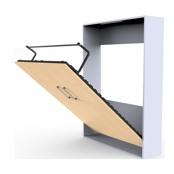
- Page 12 ATTACHING THE PISTONS TO THE FRAME Mount pistons perpendicular to the frame Secure the longer metal ends of the pistons to the frame. This end INSTALLING THE FRAME ONTO THE MOUNTING BRACKETS Cabinet MUST be secured to the wall with at least 2 studs before this step. ( 3 studs for the queen size )
- Page 13 INSTALLING THE PISTONS TO THE CABINET Tilt the frame inside past the cabinet edge to mount the pistons on the mounting brackets through the opening between the slats. FF =...
-
Page 14: Installing The Legs
INSTALLING THE LEGS The pistons are now installed, therefore do NOT operate the bed without the help of another person. Do NOT let go of the mechanism Install the temporary stoppers onto the top corners of the bed cabinet. Do not overtighten. Secure the legs to the bed frame. -
Page 15: Installing The Doors
INSTALLING THE DOOR BRACKETS 102mm 4” 102mm 4” The door brackets must point downward. Install the door brackets in alignment with the support bars on the bed frame. 256mm ” 1/16 Measurements (right) are for the placement of this hole along the doors 714mm ”... - Page 16 11.2 Attach the doors to the frame while putting weight on the frame to keep the bed open. We recommend having someone else sit on the frame during this step. For this step x 20 The bed will not stay down without the weight of a mattress and panels.
- Page 17 INSTALLING THE PERMANENT STOPPER Permanent stopper Install the stopper (not included) on the inside top of the cabinet where it will allow for the door to close flush to the front of the cabinet. INSTALLING THE MATTRESS SUPPORTS Insert the mattress supports into the designated holes on the bed frame.
- Page 18 USING THE WALL BED Pivot the leg towards the inside of the unit. Make sure The wall bed is assembled and shown in lowered that the leg is completely pivoted in position. Pull up gently to close. The leg serves as a mattress retaining system.
Need help?
Do you have a question about the EVOK 150 and is the answer not in the manual?
Questions and answers