Table of Contents
Advertisement
Quick Links
Methods and apparatus disclosed and described herein have been developed solely on company funds of Lake Shore Cryotronics, Inc.
No government or other contractual support or relationship whatsoever has existed which in any way affects or mitigates proprietary
rights of Lake Shore Cryotronics, Inc. in these developments. Methods and apparatus disclosed herein may be subject to U.S. Patents
existing or applied for. Lake Shore Cryotronics, Inc. reserves the right to add, improve, modify, or withdraw functions, design
modifications, or products at any time without notice. Lake Shore shall not be liable for errors contained herein or for incidental or
consequential damages in connection with furnishing, performance, or use of this material.
Rev. 2.8
User's Manual
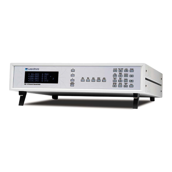
Model 460
3-Channel Gaussmeter
Lake Shore Cryotronics, Inc.
575 McCorkle Blvd.
Westerville, Ohio 43082-8888 USA
Internet Addresses:
sales@lakeshore.com
service@lakeshore.com
Visit Our Website:
www.lakeshore.com
Fax: (614) 891-1392
Telephone: (614) 891-2243
P/N 119-012
24 July 2017
Advertisement
Chapters
Table of Contents
Troubleshooting

Related Manuals for Lake Shore 460


Summary of Contents for Lake Shore 460
- Page 1 Lake Shore Cryotronics, Inc. reserves the right to add, improve, modify, or withdraw functions, design modifications, or products at any time without notice. Lake Shore shall not be liable for errors contained herein or for incidental or consequential damages in connection with furnishing, performance, or use of this material.
- Page 2 Warranty Period and the defective Product is shipped freight prepaid back to Lake Shore, Lake Shore will, at its option, either repair or replace the Product (if it is so defective) without charge for parts, service labor or associated customary return shipping cost to the Purchaser.
- Page 3 FIRMWARE LIMITATIONS Lake Shore has worked to ensure that the Model 460 firmware is as free of errors as possible, and that the results you obtain from the instrument are accurate and reliable. However, as with any computer-based software, the possibility of errors exists.
- Page 5 Lake Shore Model 460 Gaussmeter User’s Manual DECLARATION OF CONFORMITY This declaration of conformity is issued under the sole responsibility of the manufacturer. Manufacturer: Lake Shore Cryotronics, Inc. 575 McCorkle Boulevard Westerville, OH 43082 Object of the declaration: Model(s): Description:...
- Page 6 Emissions of and immunity to electromagnetic interference is now part of the design and manufacture of most electronics. To qualify for the CE Mark, the Model 460 meets or exceeds the generic requirements of the European EMC Directive 89/336/EEC as a CLASS A product. A CLASS A...
- Page 7 Lake Shore Model 460 Gaussmeter User’s Manual...
-
Page 9: Table Of Contents
Lake Shore Model 460 Gaussmeter User’s Manual TABLE OF CONTENTS Chapter/Paragraph Title Page INTRODUCTION ..............................1-1 General .............................. 1-1 Product Description ........................... 1-1 Specifications ............................ 1-4 Safety Summary ..........................1-5 Safety Symbols ..........................1-5 INSTALLATION ..............................2-1 General .............................. 2-1 Inspection and Unpacking ......................... - Page 10 C1.0 General ............................. C-1 C2.0 Theory of Operation .......................... C-1 C3.0 Hall Generator Generic Hookup ....................... C-3 C4.0 Using a Hall Generator with the Model 460 ..................C-4 C5.0 Specifications ........................... C-5 C6.0 HALLCAL.EXE Program ........................C-8 Table of Contents...
- Page 11 3-Axis Probe Tip Details ..........................5-5 Definition of Lake Shore Gamma Probe ....................... 5-5 Definition of Lake Shore 2- and 3-Axis Probes ..................... 5-6 Definition of Lake Shore Robust (Brass Stem) Probes................. 5-6 Definition of Lake Shore Transverse Probes ....................5-7 Definition of Lake Shore Tangential Probe ....................
- Page 12 Lake Shore Model 460 Gaussmeter User’s Manual LIST OF TABLES Table No. Title Page IEEE-488 Interface Program Control Properties ................... 4-8 Visual Basic IEEE-488 Interface Program ....................4-9 Quick Basic IEEE-488 Interface Program....................4-12 Serial Interface Specifications ........................4-15 Serial Interface Program Control Properties ....................4-18 Visual Basic Serial Interface Program ......................
-
Page 13: Introduction
Hall effect sensors and probes. This strength is most apparent when multiple axis measurements are required. The Model 460 is optimized for use with Lake Shore two- and three-axis probes as well as standard Hall sensors, single axis probes, and probe accessories. The instrument automatically reads data stored in the probe connector to identify probe type and capability. - Page 14 In RMS mode, the Model 460 can measure periodic AC fields from 10 to 400 Hertz. True RMS conversion is done by instrument circuitry that accommodates wave forms with crest factors up to 7.
- Page 15 Lake Shore Model 460 Gaussmeter User’s Manual Product Description (Continued) X and Y Axis with Differential Reading + 1 0 5 . 6 2 8 G DC + 8 3 . 4 1 5 G DC + 2 2 . 2 1 3 G X- Y Differential readings (X –...
-
Page 16: Specifications
0.001 G 0.01 G Configuration: Voltage output generated by DAC 30 G 0.0001 G 0.001 G Range: ±3 V; ±10 V for Model 460-10 UHS Probe Scale: User defined 30 G 0.0001 G 0.001 G Resolution: 0.366 mV of ±3 V 0.00001 G... -
Page 17: Safety Summary
Cryotronics, Inc. assumes no liability for Customer failure to comply with these requirements. The Model 460 protects the operator and surrounding area from electric shock or burn, mechanical hazards, excessive temperature, and spread of fire from the instrument. Environmental conditions outside of the conditions below may pose a hazard to the operator and surrounding area. - Page 18 Lake Shore Model 460 Gaussmeter User’s Manual This Page Intentionally Left Blank Introduction...
-
Page 19: Installation
Inspect shipping containers for external damage. Make all claims for damage (apparent or concealed) or partial loss of shipment in writing to Lake Shore within five (5) days from receipt of goods. If damage or loss is apparent, please notify the shipping agent immediately. -
Page 20: Rear Panel Definition
Lake Shore Model 460 Gaussmeter User’s Manual REAR PANEL DEFINITION This paragraph provides a description of the Model 460 rear panel connections. The rear panel consists of the line input assembly, IEEE-488 Interface Connector, Serial I/O Connector, Probe Input Connectors, and Corrected and Monitor Analog Output BNCs. This paragraph is provided for information only. -
Page 21: Line Input Assembly
CAUTION: Always turn off the instrument before making any rear panel Probe Input connections. Lake Shore probes plug into three 15 pin D-style connectors on the rear panel. Turn the instrument off before attaching a probe. Align the probe connector with the rear panel connector and push straight in to avoid bending the pins. -
Page 22: Attachment To A Hall Generator
Check power setting on fuse drawer window. Damage may occur if connected to improper voltage. 1. Check power source for proper voltage. The Model 460 operates with 100, 120, 220, or 240 (+5%, –10%) AC input voltage. If incorrect, refer to Paragraph 6.3. - Page 23 NOTE: Some Lake Shore probes come with a clear plastic sleeve to protect the probe tip when not in use. The sleeve slides up and down the probe cable. To place the probe in the zero gauss chamber, slide the protective sleeve back, exposing the probe tip, before placing the tip in the chamber.
- Page 24 Lake Shore Model 460 Gaussmeter User’s Manual Initial Setup And System Checkout Procedure (Continued) 12. If continuing the procedure with a reference magnet, ensure the probe can accommodate the range of the magnet. Use the Range key to select the proper range. Set the display for DC.
-
Page 25: Operation
DEFINITION OF FRONT PANEL CONTROLS This paragraph provides a description of the front panel controls on the Model 460. The front panel consists of two major sections: a description of the 25 front panel keys in Paragraph 3.1.1, and a description of the front panel display in Paragraph 3.1.2. - Page 26 This function is not available for Vector Magnitude. Refer to Paragraph 3.4. Auto Range Turns the Auto Range feature on and off. Allows the Model 460 to automatically select the field measurement range. This function is not available for Vector Magnitude. Refer to Paragraph 3.4.
-
Page 27: Front Panel Display
Lake Shore Model 460 Gaussmeter User’s Manual Front Panel Keypad Definitions (Continued) Escape Terminates a function without making changes to the existing settings. Press and hold the Escape key for ≈20 seconds to reset the instrument and return parameters to factory default values. Refer to Paragraph 3.15. -
Page 28: Front Panel Navigation
Lake Shore Model 460 Gaussmeter User’s Manual 3.1.3 Front Panel Navigation Information in the first line of the display pertains to Channel X, the second line to Channel Y, third line to Channel Z, and the fourth line to the Vector Magnitude. To select a function for a channel, you must first push the X, Y, Z, or Vector Magnitude key. -
Page 29: Vector Source
Lake Shore Model 460 Gaussmeter User’s Manual 3.1.5 Vector Source In addition to turning the Vector Magnitude display on or off, the source of the Vector display must also be selected. Press and hold the Vector Magnitude key until the display reads Channel ON, then press the Enter key. -
Page 30: Zero Probe
NOTE: Some Lake Shore probes are equipped with a clear plastic sleeve intended to protect the tip of the probe when not being used. The sleeve is designed to slide up and down the probe cable. -
Page 31: Select Range And Auto Range
SELECT RANGE AND AUTO RANGE Each channel of the Model 460 is capable of reading any of the Lake Shore probe types: High Stability, High Sensitivity, or Ultra-High Sensitivity. The three probes permit the Model 460 to sense fields as low as 0.01 mG and as high as 300 kG. -
Page 32: Ac/Dc And Peak/Rms
OL will also cause the Vector display to display OL. In Auto Range mode, the Model 460 selects the range with the best resolution for the field being measured. It can take up to 2 seconds for Auto Range to work, so manual ranging may be better in some conditions. -
Page 33: Filter
Care should be taken when using the filter on changing fields because it may level off peaks and slow the response of the instrument. The filter function of the Model 460 is user configurable so that desired field changes can be seen and noise blocked. The filter also acts to quiet noise within the instrument, making an additional digit of usable resolution available with the filter on in DC. - Page 34 Filter Window can be set from 1% to 10% of the present range. The Model 460 uses two different filter algorithms that result in slightly different settling time computations. For filter points from 2 to 8, a linear average is used to get the fastest possible response.
-
Page 35: Field And Temperature Compensation
Some probes also feature temperature compensation. Selecting Temperature Compensation Off will cause the Model 460 to ignore this data. Pressing the s or t keys cycles between On and Off. Push the Enter key to accept the new setting or the Escape key to leave the setting as is and return to the normal display. -
Page 36: Relative Set And Relative On/Off
Lake Shore Model 460 Gaussmeter User’s Manual RELATIVE SET AND RELATIVE ON/OFF The relative function lets the user see small variations in larger fields. The setpoint (or center) of the relative reading is set with the Relative Set key. There are two ways to enter the relative setpoint. The first method captures the field reading, nulling the present field. -
Page 37: 3.10 Alarm Set And Alarm On/Off
Use the s or t keys to cycle between audible alarm on or off. Press Enter to accept the new value or Escape to step to the next function while retaining the old setting. (Audible is a global setting and applies to all channels.) The Model 460 will then go to the next display. Se l e c t W i t h °... - Page 38 Lake Shore Model 460 Gaussmeter User’s Manual Alarm Set and Alarm On/Off (Continued) One important point to remember is that the alarm setpoints are absolute (unsigned), i.e., only the magnitude of the field reading is used. Therefore, once alarm points are specified, any reading, whether positive or negative, will trigger the alarm.
- Page 39 Lake Shore Model 460 Gaussmeter User’s Manual Alarm Set and Alarm On/Off (Continued) The following example details how the alarm operates in the Alarm “Inside” setting. The alarm inside setup is useful in situations where the user is looking for an indication of a good reading, such as incoming inspections.
-
Page 40: 3.11 Local And Interface
Press the s or t keys to increment or decrement the IEEE Address to the required number. Press Enter to accept the new number or Escape to leave the existing number. The Model 460 automatically proceeds to the IEEE-488 Terminator display as follows. -
Page 41: 3.12 Display
3.13 ANALOG OUT There are two types of analog outputs available on the rear panel of the Model 460. They are the Corrected and Monitor Analog Outputs. A single corrected analog output is provided (whose source is user definable), and three monitor outputs are provided (one for each channel). - Page 42 Lake Shore Model 460 Gaussmeter User’s Manual Corrected Analog Out (Continued) Press the Analog Out, s , or t key to cycle the arrow (→) to Def (Default). Press the Enter key. You will then see the channel selection display as follows.
- Page 43 Lake Shore Model 460 Gaussmeter User’s Manual Corrected Analog Out (Continued) Enter the numbers 1.5 on the numerical keypad and press the Enter key. A maximum output of +1.5 kG has now been placed into memory. Upon pressing Enter, the following display will appear.
-
Page 44: 3.13.2 Monitor Analog Out
1.0100 kG or greater. 3.13.2 Monitor Analog Out There are three Monitor Analog Outputs on the rear panel of the Model 460. The three outputs correspond to channels X, Y, and Z. There is no monitor output for Vector Magnitude. The Monitor Analog Outputs are real-time analog signals proportional to the magnetic field. -
Page 45: 3.14 Locking And Unlocking The Keyboard
Lake Shore Model 460 Gaussmeter User’s Manual 3.14 LOCKING AND UNLOCKING THE KEYBOARD The Model 460 front panel keyboard may be locked, preventing unauthorized changes to the settings. To lock the keyboard, press and hold the Enter key (≈10 seconds) until the following display is seen. -
Page 46: 3.15 Factory Default Settings
3.15 FACTORY DEFAULT SETTINGS If the keypad is unlocked and the Model 460 is in local mode, the user may press and hold Escape key for ≈20 seconds to return the instrument to factory default settings shown below. Other gaussmeter calibration information and probe data are not affected by this reset. -
Page 47: 3.16.2 Analog Output Control Mode
Model 460s is available at no charge. The actual output voltage and voltage resolution depends on an instrument hardware setting. In a standard Model 460, the output range of the corrected analog output is ±3 volts. A jumper is located inside the gaussmeter that can change the corrected analog output to ±10 volts. This jumper is set at the factory per the customer’s original request. -
Page 48: 3.17 Probe Considerations
Lake Shore Model 460 Gaussmeter User’s Manual 3.17 PROBE CONSIDERATIONS To avoid damage and for best results during use, the probes have a number of handling and accuracy requirements that must be observed. Changing probes is discussed in Paragraph 3.17.1. Probe handling is discussed in Paragraph 3.17.2. -
Page 49: 3.17.2 Probe Handling
45° from the base. See Figure 3-5. Force should never be applied to the tip of the probe. On all probes, do not pinch or allow cables to be struck by any heavy or sharp objects. Although damaged or severed cables should be returned to Lake Shore for repair, please understand that probes are not always repairable. -
Page 50: 3.17.3 Probe Polarity
In the DC mode of operation, the orientation of the probe affects the polarity reading of the gaussmeter. On a transverse probe, the Lake Shore name printed on the handle indicates the side for positive (+) flux entry. On an axial probe, positive (+) flux entry is always from the front of the probe. -
Page 51: 3.17.4 Probe Accuracy Considerations
Lake Shore Model 460 Gaussmeter User’s Manual 3.17.4 Probe Accuracy Considerations NOTE: Probe readings are dependent upon the angle of the sensor in relation to the magnetic field. The further from 90° the angle between the probe and the field, the greater the percentage of error. - Page 52 Lake Shore Model 460 Gaussmeter User’s Manual This Page Intentionally Left Blank 3-28 Operation...
-
Page 53: Computer Interface Operation
Cable lengths are limited to 2 meters for each device and 20 meters for the entire bus. The Model 460 can drive a bus with up to 10 loads. If more instruments or cable length is required, a bus expander must be used. -
Page 54: Ieee-488 Command Structure
EOI. To accept changes or the currently displayed setting, push Enter. To cancel changes, push Escape. Power down the Model 460 then back up again to allow other devices on the IEEE-488 bus to recognize a new Address or Terminator setting. -
Page 55: Common Commands
Most device specific commands perform functions also performed from the front panel. Model 460 device specific commands are detailed in Paragraphs 4.3.2 thru 4.3.4 and summarized in Table 4-8. -
Page 56: Status Registers
Not Used Not Used If the Service Request is enabled, any of these bits being set will cause the Model 460 to pull the SRQ management low to signal the BUS CONTROLLER. These bits are reset to zero upon a serial poll of the Status Byte Register. -
Page 57: Ieee Interface Example Programs
Operation Complete (OPC) Bit (0) – This bit is generated in response to the QOPC common command. It indicates when the Model 460 has completed all selected pending operations. 4.1.4 IEEE Interface Example Programs Two BASIC programs are included to illustrate the IEEE-488 communication functions of the instrument. - Page 58 Lake Shore Model 460 Gaussmeter User’s Manual Figure 4-1. GPIB Setting Configuration Figure 4-2. DEV 12 Device Template Configuration Remote Operation...
-
Page 59: Visual Basic Ieee-488 Interface Program Setup
Lake Shore Model 460 Gaussmeter User’s Manual 4.1.4.2 Visual Basic IEEE-488 Interface Program Setup This IEEE-488 interface program works with Visual Basic 6.0 (VB6) on an IBM PC (or compatible) with a Pentium-class processor. A Pentium 90 or higher is recommended, running Windows 95 or better. - Page 60 Lake Shore Model 460 Gaussmeter User’s Manual Table 4-1. IEEE-488 Interface Program Control Properties Current Name Property New Value Label1 Name lblExitProgram Caption Type “exit” to end program. Label2 Name lblCommand Caption Command Label3 Name lblResponse Caption Response Text1 Name...
- Page 61 Lake Shore Model 460 Gaussmeter User’s Manual Table 4-2. Visual Basic IEEE-488 Interface Program Public gSend As Boolean 'Global used for Send button state Private Sub cmdSend_Click() 'Routine to handle Send button press gSend = True 'Set Flag to True...
-
Page 62: Ieee-488 Interface Board Installation For Quick Basic Program
Lake Shore Model 460 Gaussmeter User’s Manual 4.1.4.3 IEEE-488 Interface Board Installation for Quick Basic Program This procedure works on an IBM PC (or compatible) running DOS or in a DOS window. This example uses the National Instruments GPIB-PCII/IIA card. - Page 63 Lake Shore Model 460 Gaussmeter User’s Manual IBCONF.EXE.eps Figure 4-3. Typical National Instruments GPIB Configuration from IBCONF.EXE 4-11 Remote Operation...
- Page 64 Lake Shore Model 460 Gaussmeter User’s Manual Table 4-3. Quick Basic IEEE-488 Interface Program IEEEEXAM.BAS EXAMPLE PROGRAM FOR IEEE-488 INTERFACE This program works with QuickBasic 4.0/4.5 on an IBM PC or compatible. The example requires a properly configured National Instruments GPIB-PC2 card. The REM $INCLUDE statement is necessary along with a correct path to the file QBDECL.BAS.
-
Page 65: Program Operation
Lake Shore Model 460 Gaussmeter User’s Manual 4.1.4.5 Program Operation Once either example program is running, try the following commands and observe the response of the instrument. Input from the user is shown in bold and terminators are added by the program. -
Page 66: Serial Interface Overview
Lake Shore Model 460 Gaussmeter User’s Manual SERIAL INTERFACE OVERVIEW The serial interface used in the Model 460 is commonly referred to as an RS-232C interface. RS-232C is a standard of the Electronics Industries Association (EIA) that describes one of the most common interfaces between computers and electronic equipment. -
Page 67: Hardware Support
4.2.2 Hardware Support The Model 460 interface hardware supports the following features. Asynchronous timing is used for the individual bit data within a character. This timing requires start and stop bits as part of each character so the transmitter and receiver can resynchronized between each character. Half duplex transmission allows the instrument to be either a transmitter or a receiver of data but not at the same time. -
Page 68: Message Flow Control
Lake Shore Model 460 Gaussmeter User’s Manual Message Strings (Continued) A query string is issued by the computer and instructs the instrument to send a response. The query format is: <query mnemonic><?><space><parameter data><terminators>. Query mnemonics are often the same as commands with the addition of a question mark. Parameter data is often unnecessary when sending queries. -
Page 69: Serial Interface Basic Programs
Lake Shore Model 460 Gaussmeter User’s Manual 4.2.7 Serial Interface Basic Programs Two BASIC programs are included to illustrate the serial communication functions of the instrument. The first program was written in Visual Basic. Refer to Paragraph 4.2.7.1 for instructions on how to setup the program. - Page 70 Lake Shore Model 460 Gaussmeter User’s Manual Table 4-5. Serial Interface Program Control Properties Current Name Property New Value Label1 Name lblExitProgram Caption Type “exit” to end program. Label2 Name lblCommand Caption Command Label3 Name lblResponse Caption Response Text1 Name...
- Page 71 Lake Shore Model 460 Gaussmeter User’s Manual Table 4-6. Visual Basic Serial Interface Program Public gSend As Boolean 'Global used for Send button state Private Sub cmdSend_Click() 'Routine to handle Send button press gSend = True 'Set Flag to True...
-
Page 72: Quick Basic Serial Interface Program Setup
Lake Shore Model 460 Gaussmeter User’s Manual 4.2.7.2 Quick Basic Serial Interface Program Setup The serial interface program (Table 4-7) works with QuickBasic 4.0/4.5 or Qbasic on an IBM PC (or compatible) running DOS or in a DOS window with a serial interface. It uses the COM1 communication port at 9600 Baud. - Page 73 Lake Shore Model 460 Gaussmeter User’s Manual 4.2.7.3 Program Operation Once either program is running, try the following commands and observe the response of the instrument. Input from the user is shown in bold and terminators are added by the program. The word [term] indicates the required terminators included with the response.
-
Page 74: Trouble Shooting
Lake Shore Model 460 Gaussmeter User’s Manual 4.2.8 Trouble Shooting New Installation 8. Check instrument baud rate 9. Make sure transmit (TD) signal line from the instrument is routed to receive (RD) on the computer and vice versa. (Use a null modem adapter if not). - Page 75 Lake Shore Model 460 Gaussmeter User’s Manual Table 4-8. Command Summary Command Function Page Command Function Page Common Commands ANOD Default Analog Out Cmd ..... 4-32 QCLS Clear Interface Cmd ....... 4-24 ANOD? Default Analog Out Query ....4-32 QESE Std.
-
Page 76: Common Commands
Lake Shore Model 460 Gaussmeter User’s Manual 4.3.1 Common Commands QCLS Clear Interface Command Input: QCLS[term] Remarks: Clears the bits in the Status Byte Register and Standard Event Status Register and terminates all pending operations. Clears the interface, but not the controller. The related controller command is QRST. -
Page 77: Qopc Operation Complete Cmd
Lake Shore Model 460 Gaussmeter User’s Manual Common Commands (Continued) QOPC Operation Complete Command Input: QOPC[term] Remarks: Generates an Operation Complete event in the Event Status Register upon completion of all pending selected device operations. Send it as the last command in a command string. -
Page 78: Qtst? Self-Test Query
QTST?[term] Returned: <status> Format: <status> 0 = no errors found, 1 = errors found Remarks: The Model 460 reports status based on test done at power up. QWAI Wait-to-Continue Command Input: QWAI[term] Remarks: Send QWAI as the last command in a command string followed by appropriate termination. It cannot be embedded between other commands. -
Page 79: Interface Commands
IEEE Address Command Input: ADDR <address>[term] Format: <address> An integer from 1 to 30. Address 0 and 31 are reserved. Remarks: The Model 460 is factory preset to Address 12. Refer to Paragraph 3.11. ADDR? IEEE Address Query Input: ADDR?[term] Returned: <address>[term]... -
Page 80: Fast Fast Data Mode Cmd
Lake Shore Model 460 Gaussmeter User’s Manual Interface Commands (Continued) End Or Identify (EOI) Status Command Input: END <state>[term] Format: <state> 0 = Enabled, 1 = Disabled Remarks: Sets the EOI status. When enabled, the hardware EOI line becomes active with the last byte of a transfer. -
Page 81: Term Terminator Cmd
2 = Remote Mode with Local Lockout Remarks: Press the front panel Local key to set the Model 460 to local provided the key has not been disabled by local lockout. The Model 460 powers up in local mode. Refer to Paragraph 3.11. -
Page 82: Device Specific Commands
Lake Shore Model 460 Gaussmeter User’s Manual 4.3.3 Device Specific Commands ACDC AC/DC Magnetic Field Reading Command Input: ACDC <mode>[term] Format: <mode> 0 = DC, 1 = AC Remarks: Configures the unit for AC or DC measurements. The AC field is further defined by the PRMS (Peak or RMS) command. -
Page 83: Almh Alarm High Point Cmd
Lake Shore Model 460 Gaussmeter User’s Manual Device Specific Commands (Continued) ALMH Alarm High Point Command Input: ALMH <field value>[term] Format: ±nnn.nn <field value> Returns sign, 4 or 5 digits, and places decimal point appropriate to range. Remarks: New value is entered on the same field range as the old value. Setting value to zero first will change the setting range to present display range. -
Page 84: Alml? Alarm Low Point Query
Lake Shore Model 460 Gaussmeter User’s Manual Device Specific Commands (Continued) ALML? Alarm Low Point Query Input: ALML?[term] Returned: <field value>[term] Format: ±nnn.nn (Refer to command for description) Remarks: Use ALMLM? to determine units multiplier. ALMLM? Alarm Low Point Multiplier Query... -
Page 85: Anoh? Analog Out High Setpoint Query
Lake Shore Model 460 Gaussmeter User’s Manual Device Specific Commands (Continued) ANOH? Analog Out High Setpoint Query Input: ANOH?[term] Returned: <field value>[term] Format: ±nnn.nn (Refer to command for description) Remarks: Use ANOHM? to determine units multiplier. ANOHM? Analog Out High Setpoint Multiplier Query... -
Page 86: Anos? Corrected Analog Output Query
Lake Shore Model 460 Gaussmeter User’s Manual Device Specific Commands (Continued) ANOS? Corrected Analog Output Source Query Input: ANOS?[term] Returned: <source>[term] Format: (Refer to command for description) AOCON Analog Output Control Mode Command Input: AOCON <percent>[term] Format: ±nnn.nn <percent> Sets bipolar output voltage in percent of full scale. Allows resolution of 0.01%. -
Page 87: Filt Display Filter Cmd
Lake Shore Model 460 Gaussmeter User’s Manual Device Specific Commands (Continued) FIELD? Magnetic Field Reading Query Input: FIELD?[term] Returned: <field value>[term] Format: ±nnn.nn <field value> Returns sign, 4 or 5 digits, and places decimal point appropriate to range. Remarks: Use FIELDM? to determine units multiplier and UNITS? to determine gauss or tesla units. -
Page 88: Fwin Display Filter Window Cmd
Lake Shore Model 460 Gaussmeter User’s Manual Device Specific Commands (Continued) FWIN Display Filter Window Command Input: FWIN <window>[term] Format: <points> Integer from 1 thru 10 Remarks: Sets the filter window from 1% thru 10%. The smaller the percentage, the smaller the change in magnetic field that causes the filter to restart. - Page 89 Lake Shore Model 460 Gaussmeter User’s Manual Device Specific Commands (Continued) MAXRM? Max Reading Multiplier Query Input: MAXRM?[term] Returned: <multiplier>[term] Format: <multiplier> u = micro = 10 , m = milli = 10 , (blank) = unity, k = kilo = 10 Remarks: Used with MAXR? query.
-
Page 90: Rel? Relative Mode Query
Lake Shore Model 460 Gaussmeter User’s Manual Device Specific Commands (Continued) REL? Relative Mode Query Input: REL?[term] Returned: <state>[term] Format: (Refer to command for description) RELR? Relative Mode Reading Query Input: RELR?[term] Returned: <field value>[term] Format: ±nnn.nn <field value> Returns sign, 4 or 5 digits, and places decimal point appropriate to range. -
Page 91: Probe Specific Commands
Lake Shore Model 460 Gaussmeter User’s Manual Device Specific Commands (Continued) UNIT Gauss/Tesla Units Command Input: UNIT <unit>[term] Format: <unit> G = gauss, T = tesla. Refer to Paragraph 3.8. UNIT? Gauss/Tesla Unit Query Input: UNIT?[term] Returned: <unit>[term] Format: (Refer to command for description) -
Page 92: Onoff? Probe On/Off Query
Lake Shore Model 460 Gaussmeter User’s Manual Probe Specific Commands (Continued) ONOFF? Probe On/Off Query Input: ONOFF?[term] Returned: <state>[term] Format: (Refer to command for description) SNUM? Probe Serial Number Query Input: SNUM?[term] Returned: <serial>[term] Format: annnnnnnnn <serial> The current probe serial number format is Hnnnnn, though there is room for up to a ten-character response. -
Page 93: Accessories And Probes
IEEE-488 Interface Cable. Connects Model 460 to customer-supplied computer with 4004 IEEE-488 Interface. Cable is 1 meter (3 feet) long. Rack Mounting Kit. Mounting ears and hardware to attach one Model 460 to a 483 mm RM-1 (19-inch) rack mount space. - Page 94 MAN-460 Hall Generator Cable Assembly. The MCBL Cable Assembly connects a discrete Hall generator to the Model 460 Gaussmeter. The cable ships with the HALLCAL.EXE program which permits cable PROM programming through a PC (or compatible) computer serial port. Because of the many calibration intricacies, the user is responsible for MCBL-XX measurement accuracy.
-
Page 95: Lake Shore Standard Probes
* Included with purchase of gaussmeter. LAKE SHORE STANDARD PROBES There are several types of Lake Shore Model 460 probes available: 2- and 3-Axis, Axial, Gamma, Tangential, and Transverse — each named for its Hall sensor orientation. Because the Model 460 covers such a wide magnetic field range (0.01 mG to 300 kG), three probe ranges are available: High... -
Page 96: Radiation Effects On Gaussmeter Probes
5.3.3 2-Axis and 3-Axis Probes At the tip of Lake Shore 2-Axis probes are one transverse and one axial Hall sensor. 3-Axis probes contain two transverse and one axial Hall sensor. These sensors are recessed in the non-metallic Phenolic mounting block—Phenolic permits AC and DC measurements—whereas aluminum limits probes to DC or low frequency measurements. -
Page 97: Probe Specifications
Lake Shore Model 460 Gaussmeter User’s Manual Figure 5-2. 3-Axis Probe Tip Details 5.3.4 Probe Specifications Terminology used in Figures 5-3 thru 5-10 are defined as follows: Definition of Probe Terminology Usable Full-Scale Ranges Vs. Probe Type Type HST-1 HST-2... - Page 98 Lake Shore Model 460 Gaussmeter User’s Manual 2- & 3-AXIS PROBES 2-3_Axis.eps Figure 5-4. Definition of Lake Shore 2- and 3-Axis Probes Accessories & Probes...
- Page 99 Lake Shore Model 460 Gaussmeter User’s Manual ROBUST (BRASS STEM) TRANSVERSE PROBES Brass_Transverse.eps Figure 5-5. Definition of Lake Shore Robust (Brass Stem) Transverse Probes Accessories & Probes...
- Page 100 Lake Shore Model 460 Gaussmeter User’s Manual TRANSVERSE PROBES Transverse.eps Figure 5-6. Definition of Lake Shore Transverse Probes TANGENTIAL PROBE Tangential.eps Figure 5-7. Definition of Lake Shore Tangential Probe Accessories & Probes...
- Page 101 Lake Shore Model 460 Gaussmeter User’s Manual AXIAL PROBES Axial.eps Figure 5-8. Definition of Lake Shore Axial Probes Accessories & Probes...
- Page 102 Lake Shore Model 460 Gaussmeter User’s Manual FLEXIBLE TRANSVERSE PROBES Flexible_Transverse.eps Figure 5-9. Definition of Lake Shore Flexible Transverse Probes FLEXIBLE AXIAL PROBE Flexible_Axial.eps Figure 5-10. Definition of Lake Shore Flexible Axial Probe 5-10 Accessories & Probes...
-
Page 103: Helmholtz Coil Low Field Standards
Lake Shore Model 460 Gaussmeter User’s Manual HELMHOLTZ COIL LOW FIELD STANDARDS Lake Shore offers three Helmholtz coils: 2.5-, 6-, and 12-inch diameter. Check the latest Lake Shore brochures or our website for any recent additions to this line. These coils are accurately calibrated using field standards maintained at Lake Shore. Most standards are traceable to physical standards such as a coil of carefully controlled dimensions, or in some cases, to proton resonance. - Page 104 Lake Shore Model 460 Gaussmeter User’s Manual P-460-5-12.bmp Figure 5-12. Model MH-6 Helmholtz Coil P-460-5-13.bmp Figure 5-13. Model MH-12 Helmholtz Coil 5-12 Accessories & Probes...
-
Page 105: Reference Magnets
Lake Shore Model 460 Gaussmeter User’s Manual REFERENCE MAGNETS Magnetic reference standards containing highly stable permanent magnets have been in use for many years. The highest quality units are usually shielded from external magnetic effects and use Alnico V or VI magnets for long-term stability. - Page 106 Lake Shore Model 460 Gaussmeter User’s Manual NOTE: Use care to ensure the Zero Gauss Chamber does not become magnetized. Using a magnetized chamber to zero a probe can lead to erroneous field readings. It is a good practice to periodically degauss the chamber. If no professional degausser is available, a bulk tape degausser (Verity VS250, Data Devices PF211, or equivalent) may be used.
- Page 107 Lake Shore Model 460 Gaussmeter User’s Manual (See Figure 6-6 for wiring details.) C-460-5-17.eps Figure 5-17. Model 4001 RJ-11 Cable Assembly (See Figure 6-7 for wiring details.) C-460-5-18.eps Figure 5-18. Model 4002 RJ-11 to DB-25 Adapter (See Figure 6-8 for wiring details.) C-460-5-19.eps...
-
Page 109: Service
Paragraph 6.5, optional serial interface cable and adapters in Paragraph 6.6, operating software EPROM replacement in Paragraph 6.7, and error messages in Paragraph 6.8. There are no field serviceable parts inside the Model 460. Contact Lake Shore about specific problems with the Model 460. -
Page 110: Identification Of Electrostatic Discharge Sensitive Components
Lake Shore Model 460 Gaussmeter User’s Manual 6.2.1 Identification of Electrostatic Discharge Sensitive Components The following are various industry symbols used to label components as ESDS. 6.2.2 Handling Electrostatic Discharge Sensitive Components Observe all precautions necessary to prevent damage to ESDS components before attempting installation. -
Page 111: Fuse Replacement
Lake Shore Model 460 Gaussmeter User’s Manual F-460-6-1.eps Figure 6-1. Power Fuse Access FUSE REPLACEMENT Below is the procedure to remove and replace a line fuse. There are two basic power configurations: U.S. and International. Units produced for use in the U.S. have a single fuse on the hot. Units produced for International use have a double fuse for the hot and neutral. -
Page 112: Rear Panel Connector Definitions
Lake Shore Model 460 Gaussmeter User’s Manual REAR PANEL CONNECTOR DEFINITIONS The connectors on the rear panel of the Model 460 Gaussmeter are detailed in Figures 6-2 thru 6-4. Additional details for the IEEE-488 connector is provided in Paragraph 6.5.1. -
Page 113: Ieee-488 Interface Connector
6.5.1 IEEE-488 INTERFACE CONNECTOR Connect to the IEEE-488 Interface connector on the Model 460 rear with cables specified in the IEEE-488-1978 standard document. The cable has 24 conductors with an outer shield. The connectors are 24-way Amphenol 57 Series (or equivalent) with piggyback receptacles to allow daisy-chaining in multiple device systems. -
Page 114: Optional Serial Interface Cable And Adapters
Lake Shore Model 460 Gaussmeter User’s Manual OPTIONAL SERIAL INTERFACE CABLE AND ADAPTERS To aid in Serial Interface troubleshooting, Figures 6-6 thru 6-8 show wiring information for the optional cable assembly and the two mating adapters. C-460-6-6.eps Figure 6-6. Model 4001 RJ-11 Cable Assembly Wiring Details C-460-6-7.eps... -
Page 115: Operating Software Eprom Replacement
Lake Shore Model 460 Gaussmeter User’s Manual OPERATING SOFTWARE EPROM REPLACEMENT The operating software for the Model 460 is contained on one Erasable Programmable Read Only Memory (EPROM) Integrated Circuit (IC). The EPROM is numbered U36 and located just behind the microprocessor IC (U31). -
Page 116: Error Messages
Error 2 condition. Contact Lake Shore service for repair or calibration. If the keyboard locks up, hold Escape for about 20 seconds to reset the Model 460 to factory defaults. The gaussmeter then requires the user to re-enter setpoints and zero the probe. -
Page 117: Appendix A - Glossary Of Terminology
Lake Shore Model 460 Gaussmeter User’s Manual APPENDIX A GLOSSARY OF TERMINOLOGY accuracy. The degree of correctness with which a measured value agrees with the true value. electronic accuracy. The accuracy of an instrument independent of the sensor. sensor accuracy. The accuracy of a temperature sensor and its associated calibration or its ability to match a standard curve. - Page 118 A feedback control system where the feedback device (sensor) and control actuator (heater) are joined by a digital processor. In Lake Shore controllers the heater output is maintained as a variable DC current source. digital data. Pertaining to data in the form of digits or interval quantities. Contrast with analog data.
- Page 119 Lake Shore Model 460 Gaussmeter User’s Manual gilbert (Gb). A cgs electromagnetic unit of the magnetomotive force required to produce one maxwell of magnetic flux in a magnetic circuit of unit reluctance. One gilbert is equal to 10/4π ampere-turn. Named for William Gilbert (1540 – 1603), an English physicist who hypothesized that the Earth is a magnet.
- Page 120 Lake Shore Model 460 Gaussmeter User’s Manual load regulation. A steady-state decrease of the value of the specified variable resulting from a specified increase in load, generally from no-load to full-load unless otherwise specified. M. Symbol for magnetization. See magnetization.
- Page 121 Lake Shore Model 460 Gaussmeter User’s Manual –6 ppm. Parts per million, e.g., 4 x 10 is four parts per million. precision. Careful measurement under controlled conditions which can be repeated with similar results. See repeatability. Also means that small differences can be detected and measured with confidence. See resolution.
- Page 122 Lake Shore Model 460 Gaussmeter User’s Manual temperature scales. See Kelvin Scale, Celsius Scale, and ITS-90. Proper metric usage requires that only kelvin and degrees Celsius be used. However, since degrees Fahrenheit is in such common use, all three scales are delineated as...
- Page 123 Lake Shore Model 460 Gaussmeter User’s Manual APPENDIX B UNITS FOR MAGNETIC PROPERTIES Table B-1. Conversion from CGS to SI Units Gaussian Conversion SI and Quantity Symbol and CGS emu Factor, C Rationalized mks Magnetic flux density, tesla (T), Wb/m...
- Page 124 Lake Shore Model 460 Gaussmeter User’s Manual Table B-2. Recommended SI Values for Physical Constants Quantity Symbol Value (SI units) µ Permeability of Vacuum 4π × 10 Speed of Light in Vacuum 2.9979 × 10 ε Permitivity of Vacuum = (µ...
-
Page 125: Appendix Chall Generators
Hall Generator theory of operation is detailed in Paragraph C2.0. Generic Hall generator hookup is detailed in Paragraph C3.0. Hookup to a Model 460 Gaussmeter is discussed in Paragraph C4.0. Specifications of the various available Hall generators are detailed in Paragraph C5.0. - Page 126 Lake Shore Model 460 Gaussmeter User’s Manual C-460-C-1.eps Figure C-1. Hall Generator Theory C2.2 ORIENTATION Hall generators come in two main configurations, axial and transverse. Transverse devices are generally thin and rectangular in shape. They are applied successfully in magnetic circuit gaps, surface measurements and general open field measurements.
-
Page 127: C3.0 Hall Generator Generic Hookup
Device signal levels will be in the range of microvolts to hundreds of millivolts. In this case, a separate precision current source (Lake Shore Model 120CS or equivalent) is necessary. See Figure C-3. CAUTION: The four Hall generator leads connect to four points on a sheet of semiconductor material having different potentials. -
Page 128: C4.0 Using A Hall Generator With The Model 460
30 Ω. 2. Because the Model 460 input impedance is 420 Ω, there is a voltage drop due to lead resistance in series with the gaussmeter input. The Lake Shore Hall generator sensitivity given on the data sheet is basically with no lead resistance. -
Page 129: C5.0 Specifications
C5.0 SPECIFICATIONS This section covers three types of Hall generators available from Lake Shore: HGCA & HGCT Series Cryogenic Hall generators (Figures C-5 and C-6) with specifications (Table C-1), HGA Series Axial Hall generators (Figures C-5 and C-7) with specifications (Table C-2), and HGT Series Transverse Hall generators (Figures C-8 thru C-10) with specifications (Table C-3). - Page 130 Lake Shore Model 460 Gaussmeter User’s Manual C-460-C-7.eps Figure C-7. Transverse Hall Generator HGT-1010 Dimensions Table C-2. Axial Hall Generator Specifications Axial HGA-3010 HGA-3030 Description Instrumentation quality axial; low Instrumentation quality axial; phenolic temperature coefficient; phenolic package package Active area (approximate) 0.030 inch diameter circle...
- Page 131 Lake Shore Model 460 Gaussmeter User’s Manual Table C-3. Transverse Hall Generator Specifications Transverse HGT-1010 HGT-3010 HGT-3030 Description General purpose Instrumentation quality Instrumentation quality transverse; 0.020 inch thick transverse; low temperature transverse ceramic package coefficient; ceramic package Active area (approximate) 0.040 inch diameter circle...
-
Page 132: C6.0 Hallcal.exe Program
• Operation: 1. Set the Lake Shore Model 460 Gaussmeter to 300 Baud. Refer Paragraph 3.11 of this User’s Manual on how to set the Gaussmeter to communicate at 300 Baud. 2. Insert the 3.5-inch disk and type in the default drive (A: or B:).
Need help?
Do you have a question about the 460 and is the answer not in the manual?
Questions and answers