Table of Contents
Advertisement
Methods and apparatus disclosed and described herein have been developed solely on company funds of Lake Shore Cryotronics, Inc.
No government or other contractual support or relationship whatsoever has existed which in any way affects or mitigates proprietary
rights of Lake Shore Cryotronics, Inc. in these developments. Methods and apparatus disclosed herein may be subject to U.S. Patents
existing or applied for. Lake Shore Cryotronics, Inc. reserves the right to add, improve, modify, or withdraw functions, design
modifications, or products at any time without notice. Lake Shore shall not be liable for errors contained herein or for incidental or
consequential damages in connection with furnishing, performance, or use of this material.
Rev. 1.5
User's Manual
Model 421
Gaussmeter
Lake Shore Cryotronics, Inc.
575 McCorkle Boulevard
Westerville, Ohio 43082-8888 USA
E-Mail Addresses:
sales@lakeshore.com
service@lakeshore.com
Visit Our Website:
www.lakeshore.com
Fax: (614) 891-1392
Telephone: (614) 891-2243
P/N 119-030
18 March 2004
Advertisement
Table of Contents

Related Manuals for Lake Shore Model 421


Summary of Contents for Lake Shore Model 421
- Page 1 Lake Shore Cryotronics, Inc. reserves the right to add, improve, modify, or withdraw functions, design modifications, or products at any time without notice. Lake Shore shall not be liable for errors contained herein or for incidental or consequential damages in connection with furnishing, performance, or use of this material.
- Page 2 Copyright © 1999, 2000, 2003, and 2004 by Lake Shore Cryotronics, Inc. All rights reserved. No portion of this manual may be reproduced, stored in a retrieval system, or transmitted, in any form or by any means, electronic, mechanical,...
- Page 3 Lake Shore Model 421 Gaussmeter User’s Manual DECLARATION OF CONFORMITY Lake Shore Cryotronics, Inc. 575 McCorkle Blvd. Westerville OH 43082-8888 USA hereby declare that the equipment specified conforms to the following Directives and Standards: Application of Council Directives: ......73/23/EEC 89/336/EEC Standards to which Conformity is declared: ....
- Page 4 Emissions of and immunity to electromagnetic interference is now part of the design and manufacture of most electronics. To qualify for the CE Mark, the Model 421 meets or exceeds the generic requirements of the European EMC Directive 89/336/EEC as a CLASS A product. A Class A product...
-
Page 5: Table Of Contents
Lake Shore Model 421 Gaussmeter User’s Manual TABLE OF CONTENTS Chapter/Paragraph Title Page INTRODUCTION ............................ 1-1 GENERAL ........................... 1-1 PRODUCT DESCRIPTION....................1-1 SPECIFICATIONS ......................1-3 SAFETY SUMMARY......................1-4 SAFETY SYMBOLS......................1-4 INSTALLATION ............................. 2-1 GENERAL ........................... 2-1 INSPECTION AND UNPACKING ..................2-1 REPACKAGING FOR SHIPMENT .................. - Page 6 Active Area ........................C-1 C2.2 Orientation........................C-2 C2.3 Handling .......................... C-3 C2.4 Polarity..........................C-3 C2.5 Lead Configurations ......................C-3 C3.0 HALL GENERATOR GENERIC HOOKUP................. C-3 C4.0 USING A HALL GENERATOR WITH THE MODEL 421 ........... C-4 C5.0 SPECIFICATIONS......................C-5 C6.0 HALLCAL.EXE PROGRAM....................C-8...
- Page 7 Probe Orientation For Positive Measurement ................3-14 Effect Of Angle On Measurements ..................... 3-15 Definition of Lake Shore Gamma Probe..................5-4 Definition of Lake Shore Robust (Brass Stem) Transverse Probes ..........5-4 Definition of Lake Shore Transverse Probes................5-5 Definition of Lake Shore Tangential Probe................... 5-5 Definition of Lake Shore Axial Probes ..................
- Page 8 Lake Shore Model 421 Gaussmeter User’s Manual LIST OF TABLES Table No. Title Page Serial Interface Specifications .......................4-2 Serial Interface Program Control Properties .................4-5 Visual Basic Serial Interface Program...................4-6 Quick Basic Serial Interface Program ...................4-7 Serial Interface Commands......................4-10 Conversion from CGS to SI Units ....................B-1 Recommended SI Values for Physical Constants................
-
Page 9: Introduction
• Max Hold and Relative Reading. • Alarm with Relay. If you have just received your new Model 421, please proceed to Chapter 2 and become familiar with the installation instructions. Complete and detailed instrument and probe operational information is contained in Chapter 3. - Page 10 Refer to Paragraph 5.2 for a complete list. Lake Shore probes are factory calibrated for accuracy and interchangeability. Calibration data is loaded into a PROM located in the probe connector so that it does not have to be entered by the user. Lake Shore can also custom design a probe to meet your specific application requirements.
-
Page 11: Specifications
Lake Shore Model 421 Gaussmeter User’s Manual SPECIFICATIONS General Measurement Interfaces Number Of Inputs: 1 RS-232C Capabilities: Update Rate: 5 readings per second on display; Baud: 300, 1200, 9600 up to 18 readings with serial interface Connector: 9 pin D style, DTE configuration... -
Page 12: Safety Summary
Shore Cryotronics, Inc. assumes no liability for customer failure to comply with these requirements. The Model 421 protects the operator and surrounding area from electric shock or burn, mechanical hazards, excessive temperature, and spread of fire from the instrument. Environmental conditions outside of the conditions below may pose a hazard to the operator and surrounding area. -
Page 13: Installation
Inspect shipping containers for external damage. All claims for damage (apparent or concealed) or partial loss of shipment must be made in writing to Lake Shore within five (5) days from receipt of goods. If damage or loss is apparent, please notify the shipping agent immediately. -
Page 14: Rear Panel Definition
Lake Shore Model 421 Gaussmeter User’s Manual REAR PANEL DEFINITION This paragraph provides a description of the Model 421 rear panel connections. The rear panel consists of the line input assembly, Serial I/O Connector, Probe Input Connector, Corrected and Monitor Analog Output BNCs, and Relay Terminal Block. -
Page 15: Line Input Assembly
CAUTION: Always turn off the instrument before making any rear panel Probe Input connections. Lake Shore probes plug into the 15 pin D-style connector on the Model 421 rear panel. Turn the instrument off before attaching a probe. See Figure 8-3 for pin definitions. -
Page 16: Attachment To A Hall Generator
RELAY TERMINAL BLOCK The Model 421 has a single relay output that follows the alarm state. The relay outputs have a detachable 3-pin terminal block connector. The connector (included with the Model 421) can be removed from its socket for convenient installation of wires. The connector manufacturer indicates that up to 12 AWG stranded copper wire can be used with the connector. -
Page 17: Initial Setup And System Checkout Procedure
Model 421. Also check the power setting on the window in the fuse drawer. Damage to unit may occur if connected to improper voltage. 1. Check power source for proper voltage. The Model 421 operates with 100, 120, 220, or 240 (+5%, –10%) AC input voltage. - Page 18 Lake Shore Model 421 Gaussmeter User’s Manual INITIAL SETUP AND SYSTEM CHECKOUT PROCEDURE (Continued) 10. Press the Enter key. The *CALIBRATING* message will briefly be displayed, followed by a return to the normal display. NOTE: If the unit has performed well to this point, the unit is functioning properly. If you have a reference magnet available, you can continue with the test using the magnet to verify the accuracy of the Model 421.
-
Page 19: Operation
This chapter describes Model 421 Gaussmeter operation. The front panel controls are described in Paragraph 3.1. Paragraphs 3.2 thru 3.14 describe the various front panel functions in detail. Model 421 default settings are defined in Paragraph 3.15. Finally, Paragraph 3.16 provides probe handling considerations. -
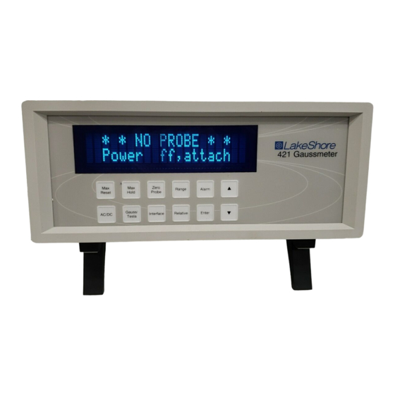
Page 20: Front Panel Display
Press and hold to adjust the brightness of the vacuum florescent display. Interface The Serial Interface baud rate of the Model 421 transmissions may be changed from 300, 1200, or 9600. Press and hold to initiate Fast Data Mode from the front panel. Alarm Turns alarm feature on or off and allows entry of alarm setpoints. -
Page 21: General Keypad Operation
When tesla is selected, the Model 421 displays AC or DC field values followed by T for tesla, mT for millitesla, or µT for microtesla. Field values available over the Serial Interface are formatted accordingly. -
Page 22: Ac/Dc
Frequency response and noise dominate the error present in AC mode. The Model 421 has a predictable frequency response which is illustrated in Figure 3-3. -
Page 23: Manual Range And Auto Range
Enter key to accept the new setting. In Auto Range mode, the Model 421 selects the range with the best resolution for the field being measured. It can take up to 2 seconds for Auto Range to work, so manual ranging may be better in some conditions. -
Page 24: Zero Probe
Lake Shore Model 421 Gaussmeter User’s Manual ZERO PROBE The zero probe function is used to null (cancel) out the zero offset of the probe or small magnetic fields. It is normally used in conjunction with the zero gauss chamber, but may also be used with an open probe (registering the local Earth magnetic field). -
Page 25: Relative
Lake Shore Model 421 Gaussmeter User’s Manual RELATIVE The relative function lets the user see small variations in larger fields. The setpoint (or center) of the relative reading is set when pressing the Relative key. This captures the current reading and effectively nulls the present field. - Page 26 Lake Shore Model 421 Gaussmeter User’s Manual ALARM AND RELAY (Continued) When the alarm is turned on, two additional setting screens will appear for high and low alarm setpoints. These values establish the limit for an error condition or the pass/fail limits for magnet testing.
- Page 27 Press Enter to accept the changes. Model 421 can be configured to display pass or fail when it is used during repetitive magnet testing or sorting operations. The sort message can be turned on or off as necessary and does not affect other operations of the alarm feature.
-
Page 28: 3.10 Analog Outputs
0.75 kG, the following diagram illustrates when the alarm would be active or normal. 3.10 ANALOG OUTPUTS There are two analog outputs available on the rear panel of the Model 421. They are the Corrected and Monitor Analog Outputs. Both outputs use BNC connectors with the center conductor carrying the signal and the outer portion the ground. -
Page 29: 3.11 Interface Parameters
Serial Interface. While the corrected analog output update rate does correspond to the Fast Data Mode, the front panel display will not operate in this mode. When the Model 421 is operating in Fast Data Mode, the user will see the following front panel display: Fast Data Mode There are two methods for placing the instrument in Fast Data Mode: from the front panel or via the Serial Interface. -
Page 30: 3.13 Locking And Unlocking The Keypad
3.13 LOCKING AND UNLOCKING THE KEYPAD The Model 421 front panel keypad may be locked, preventing inadvertent changes to the settings. To lock the keypad, press and hold the Max Hold key (≈10 seconds) until the following display is seen. -
Page 31: 3.16 Probe Considerations
45° from the base. See Figure 3-4. Force should never be applied to the tip of the probe. On all probes, do not pinch or allow cables to be struck by any heavy or sharp objects. Although damaged or severed cables should be returned to Lake Shore for repair, please understand that probes are not always repairable. -
Page 32: 3.16.3 Probe Operation
In the DC mode of operation, the orientation of the probe affects the polarity reading of the gaussmeter. On a transverse probe, the Lake Shore name printed on the handle indicates the side for positive (+) flux entry. On an axial probe, positive (+) flux entry is always from the front of the probe. -
Page 33: 3.16.4 Probe Accuracy Considerations
Lake Shore Model 421 Gaussmeter User’s Manual 3.16.4 Probe Accuracy Considerations NOTE: Probe readings are dependent upon the angle of the sensor in relation to the magnetic field. The farther from 90° the angle between the probe and the field, the greater the percentage of error. - Page 34 Lake Shore Model 421 Gaussmeter User’s Manual This Page Intentionally Left Blank 3-16 Operation...
-
Page 35: Remote Operation
Paragraph 4.2. SERIAL INTERFACE OVERVIEW The serial interface used in the Model 421 is commonly referred to as an RS-232C interface. RS-232C is a standard of the Electronics Industries Association (EIA) that describes one of the most common interfaces between computers and electronic equipment. -
Page 36: Hardware Support
4.1.2 Hardware Support The Model 421 interface hardware supports the following features. Asynchronous timing is used for the individual bit data within a character. This timing requires start and stop bits as part of each character so the transmitter and receiver can resynchronized between each character. Half duplex transmission allows the instrument to be either a transmitter or a receiver of data but not at the same time. -
Page 37: Message Flow Control
Lake Shore Model 421 Gaussmeter User’s Manual Message Strings (Continued) A query string is issued by the computer and instructs the instrument to send a response. The query format is <query mnemonic><?><space><parameter data><terminators>. Query mnemonics are often the same as commands with the addition of a question mark. Parameter data is often unnecessary when sending queries. -
Page 38: Serial Interface Basic Programs
Lake Shore Model 421 Gaussmeter User’s Manual 4.1.7 Serial Interface Basic Programs Two BASIC programs are included to illustrate the serial communication functions of the instrument. The first program was written in Visual Basic. Refer to Paragraph 4.1.7.1 for instructions on how to setup the program. -
Page 39: Serial Interface Program Control Properties
Lake Shore Model 421 Gaussmeter User’s Manual Table 4-2. Serial Interface Program Control Properties Current Name Property New Value Label1 Name lblExitProgram Caption Type “exit” to end program. Label2 Name lblCommand Caption Command Label3 Name lblResponse Caption Response Text1 Name... -
Page 40: Visual Basic Serial Interface Program
Lake Shore Model 421 Gaussmeter User’s Manual Table 4-3. Visual Basic Serial Interface Program Public gSend As Boolean 'Global used for Send button state Private Sub cmdSend_Click() 'Routine to handle Send button press gSend = True 'Set Flag to True... -
Page 41: Quick Basic Serial Interface Program
Lake Shore Model 421 Gaussmeter User’s Manual 4.1.7.2 Quick Basic Serial Interface Program Setup The serial interface program (Table 4-4) works with QuickBasic 4.0/4.5 or Qbasic on an IBM PC (or compatible) running DOS or in a DOS window with a serial interface. It uses the COM1 communication port at 9600 Baud. - Page 42 Lake Shore Model 421 Gaussmeter User’s Manual 4.1.7.3 Program Operation Once either program is running, try the following commands and observe the response of the instrument. Input from the user is shown in bold and terminators are added by the program. The word [term] indicates the required terminators included with the response.
-
Page 43: Troubleshooting
Lake Shore Model 421 Gaussmeter User’s Manual 4.1.8 Trouble Shooting New Installation 1. Check instrument baud rate 2. Make sure transmit (TD) signal line from the instrument is routed to receive (RD) on the computer and vice versa. (Use a null modem adapter if not). -
Page 44: Interface Commands
Lake Shore Model 421 Gaussmeter User’s Manual Table 4-5. Serial Interface Commands Command Function Page Command Function Page Interface Commands FAST Fast Data Mode Command ....4-15 Query Identification *......4-11 QIDN? FAST? Fast Data Mode Query ......4-15 Reset Instrument ........4-11 QRST FIELD? Field Reading Query ......4-15... - Page 45 Lake Shore Model 421 Gaussmeter User’s Manual 4.2.1 Interface Commands Q IDN? Identification Query Input: QIDN?[term] Returned: <manufacturer>,<model>,0,<date>[term] Format: aaaa,aaaaaaaa,n,mmddyy <manufacture> Manufacturer ID <model> Instrument model number Indicates no serial number included <date> Instrument firmware revision date Example: LSCI,MODEL421,0,070199 Q RST...
- Page 46 Lake Shore Model 421 Gaussmeter User’s Manual 4.2.2 Device Specific Commands ACDC AC or DC Field Measurement Command Input: ACDC <mode>[term] Format: <mode> 0 = DC, 1 = AC. Refer to Paragraph 3.3. ACDC? AC or DC Field Measurement Query...
- Page 47 Lake Shore Model 421 Gaussmeter User’s Manual Device Specific Commands (Continued) ALMH? High Alarm Setpoint Query Input: ALMH?[term] Returned: <field value>[term] Format: ±nnn.nn (Refer to command for description) Remarks: Use ALMHM? to determine units multiplier. ALMHM? High Alarm Setpoint Multiplier Query...
- Page 48 Lake Shore Model 421 Gaussmeter User’s Manual Device Specific Commands (Continued) ALMLM? Low Alarm Setpoint Multiplier Query Input: ALMLM?[term] Returned: <multiplier>[term] Format: <multiplier> µ = micro = 10 , m = milli = 10 , (blank) = unity, k = kilo = 10 Remarks: Used with ALML? query.
- Page 49 Lake Shore Model 421 Gaussmeter User’s Manual Device Specific Commands (Continued) BRIGT? Front Panel Display Brightness Query Input: BRIGT?[term] Returned: <brightness>[term] Format: (Refer to command for description) FAST Fast Data Mode Command Input: FAST <state>[term] Format: <state> 0 = Off, 1 = On Remarks: Fast Data Mode reaches data rates up to 18 readings per second via the Serial Interface with a corresponding increase in corrected analog output.
- Page 50 Lake Shore Model 421 Gaussmeter User’s Manual Device Specific Commands (Continued) LOCK Front Panel Keypad Lock Command Input: LOCK <state>[term] Format: <state> 0 = Unlocked, 1 = Locked Remarks: Locks out all front panel entries except pressing the Alarm key to silence alarms. Refer to Paragraph 3.13.
- Page 51 Lake Shore Model 421 Gaussmeter User’s Manual Device Specific Commands (Continued) RANGE Manual Range Command Input: RANGE <range>[term] Format: <range> 0 = first range (highest) , 1 = second range, 2 = third range, 3 = fourth range (lowest) Remarks: Range depends on type of probe installed. There are four ranges possible for each probe.
- Page 52 Lake Shore Model 421 Gaussmeter User’s Manual Device Specific Commands (Continued) RELS Relative Mode Setpoint Command Input: RELS <setpoint>[term] Format: nnn.nn <setpoint> Relative mode setpoint value with up to 5 digits resolution. Remarks: New value is entered on the same field range as the old value. Setting value to zero first will change the setting range to present display range.
- Page 53 Lake Shore Model 421 Gaussmeter User’s Manual Device Specific Commands (Continued) UNIT Gauss or Tesla Unit Command Input: UNIT <unit>[term] Format: <unit> G = gauss, T = tesla. Refer to Paragraph 3.2. UNIT? Gauss or Tesla Unit Query Input: UNIT?[term] Returned: <unit>[term]...
- Page 54 Lake Shore Model 421 Gaussmeter User’s Manual This Page Intentionally Left Blank 4-20 Remote Operation...
-
Page 55: Accessories And Probes
ACCESSORIES AND PROBES GENERAL This chapter provides lists of Model 421 Gaussmeter accessories and probes. Accessories are described in Paragraph 5.1. Probes are described in Paragraph 5.2. Helmholtz coils are described in Paragraph 5.3. Finally, reference magnets are described in Paragraph 5.4. - Page 56 Half-Rack Mounting Kit for One Gaussmeter. Half-length mounting panel and mounting RM-1/2 ears to attach a Model 421 to a 483 mm (19-inch) rack mount space. See Figure 5-14. Rack Mounting Shelf for Two Gaussmeters. Mounting shelf to attach two Model 421 RM-2 Gaussmeters to a 483 mm (19-inch) rack mount space.
-
Page 57: Lake Shore Standard Probes
Model 421 Gaussmeter. Examples include Axial, Flexible Axial, Transverse, Flexible Transverse, Robust Transverse, Tangential, and the Gamma Probe. Because the Model 421 covers such a wide magnetic field range (0.01 mG to 300 kG), three probe ranges are available: High Stability (HST), High Sensitivity (HSE), and Ultra-High Sensitivity (UHS). -
Page 58: Probe Specifications
UHS = Ultra-High Sensitivity Probe 300 kG — 30 kG — GAMMA PROBE Gamma.eps Figure 5-1. Definition of Lake Shore Gamma Probe ROBUST (BRASS STEM) TRANSVERSE PROBES Brass_Transverse.eps Figure 5-2. Definition of Lake Shore Robust (Brass Stem) Transverse Probes Accessories and Probes... -
Page 59: Definition Of Lake Shore Transverse Probes
Lake Shore Model 421 Gaussmeter User’s Manual TRANSVERSE PROBES * One probe is included with the purchase of the Model 421. Model numbers shown in bold are the probes available to choose from. Transverse.eps Figure 5-3. Definition of Lake Shore Transverse Probes TANGENTIAL PROBE Tangential.eps... -
Page 60: Definition Of Lake Shore Axial Probes
Lake Shore Model 421 Gaussmeter User’s Manual AXIAL PROBES * One probe is included with the purchase of the Model 421. Model numbers shown in bold are the probes available to choose from. Axial.eps Figure 5-5. Definition of Lake Shore Axial Probes... -
Page 61: Definition Of Lake Shore Flexible Transverse Probes
Lake Shore Model 421 Gaussmeter User’s Manual FLEXIBLE TRANSVERSE PROBES Flexible_Transverse.eps Figure 5-6. Definition of Lake Shore Flexible Transverse Probes FLEXIBLE AXIAL PROBE Flexible_Axial.eps Figure 5-7. Definition of Lake Shore Flexible Axial Probe Accessories and Probes... -
Page 62: Helmholtz Coil Low Field Standards
Lake Shore Model 421 Gaussmeter User’s Manual HELMHOLTZ COIL LOW FIELD STANDARDS Lake Shore offers three Helmholtz coils: 2.5-, 6-, and 12-inch diameter. Check the latest Lake Shore brochures or our website for any recent additions to this line. These coils are accurately calibrated using field standards maintained at Lake Shore. Most standards are traceable to physical standards such as a coil of carefully controlled dimensions, or in some cases, to proton resonance. -
Page 63: Model Mh-6 Helmholtz Coil
Lake Shore Model 421 Gaussmeter User’s Manual P-421-5-09.bmp Figure 5-9. Model MH-6 Helmholtz Coil P-421-5-10.bmp Figure 5-10. Model MH-12 Helmholtz Coil Accessories and Probes... -
Page 64: Reference Magnets
Lake Shore Model 421 Gaussmeter User’s Manual REFERENCE MAGNETS Magnetic reference standards containing highly stable permanent magnets have been in use for many years. The highest quality units are usually shielded from external magnetic effects and use Alnico V or VI magnets for long-term stability. -
Page 65: Model 4065 Large Zero Gauss Chamber
Lake Shore Model 421 Gaussmeter User’s Manual NOTE: Use care to ensure the Zero Gauss Chamber does not become magnetized. Using a magnetized chamber to zero a probe can lead to erroneous field readings. It is a good practice to periodically degauss the chamber. If no professional degausser is available, a bulk tape degausser (Verity VS250, Data Devices PF211, or equivalent) may be used. -
Page 66: Model Rm-1/2 Rack-Mount Kit
Lake Shore Model 421 Gaussmeter User’s Manual RM12_Rack.eps Figure 5-14. Model RM-1/2 Rack-Mount Kit 5-12 Accessories and Probes... -
Page 67: Model Rm-2 Dual Rack-Mount Shelf
Lake Shore Model 421 Gaussmeter User’s Manual RM2_Dual_Rack.eps Figure 5-15. Model RM-2 Dual Rack-Mount Shelf Accessories and Probes 5-13... - Page 68 Lake Shore Model 421 Gaussmeter User’s Manual This Page Intentionally Left Blank 5-14 Accessories and Probes...
-
Page 69: Service
Paragraph 6.5, top of enclosure remove and replace procedure in Paragraph 6.6, EPROM replacement in Paragraph 6.7, and error messages in Paragraph 6.8. There are no field serviceable parts inside the Model 421. Contact Lake Shore about specific problems with the Model 421. -
Page 70: Identification Of Electrostatic Discharge Sensitive Components
Lake Shore Model 421 Gaussmeter User’s Manual 6.2.1 Identification of Electrostatic Discharge Sensitive Components Below are various industry symbols used to label components as ESDS: 6.2.2 Handling Electrostatic Discharge Sensitive Components Observe all precautions necessary to prevent damage to ESDS components before attempting installation. -
Page 71: Fuse Replacement
Lake Shore Model 421 Gaussmeter User’s Manual F-421-6-1.eps Figure 6-1. Power Fuse Access FUSE REPLACEMENT Below is the procedure to remove and replace a line fuse. There are two basic power configurations: U.S. and International. Units produced for use in the U.S. have a single fuse on the hot. Units produced for International use have a double fuse for the hot and neutral. -
Page 72: Rear Panel Connector Definitions
Lake Shore Model 421 Gaussmeter User’s Manual REAR PANEL CONNECTOR DEFINITIONS The connectors on the rear panel of the Model 421 Gaussmeter are detailed in Figures 6-2 thru 6-5. Additional details for various external serial cables are provided in Paragraphs 6.5 1. -
Page 73: Relay Terminal Block Details
Lake Shore Model 421 Gaussmeter User’s Manual Slides into RELAY slot at rear of Model 421 Use screwdriver to lock or unlock wires Terminal Block Connector Lake Shore P/N 106-741 Insert wire into slot N C C C-421-6-4.eps DESCRIPTION Normally Closed (NC) -
Page 74: Serial Interface Cable Wiring
Lake Shore Model 421 Gaussmeter User’s Manual 6.5.1 Serial Interface Cable Wiring The following are suggested cable wiring diagrams for connecting the Model 421 Serial Interface to various Customer Personal Computers (PCs). Model 421 to PC Serial Interface – PC with DE-9P... -
Page 75: Top Of Enclosure Removal And Replacement
7. Turn power switch On (l). EPROM REPLACEMENT The operating software for the Model 421 is contained on one Erasable Programmable Read Only Memory (EPROM) Integrated Circuit (IC). The reference designator for the EPROM is U36, Lake Shore Part Number 113-591. The EPROM has a sticker on top labeled with “M421.HEX” and the date. Use the following procedure to replace the EPROM. -
Page 76: Error Messages
Figure 6-6. Location of Operation Software EPROM and Analog Output Jumper ERROR MESSAGES The following is a list of Model 421 error messages that may be seen during normal operation. Field range has been exceeded. Refer to Paragraph 3.5 to change Range. -
Page 77: Appendix A - Glossary Of Terminology
Lake Shore Model 421 Gaussmeter User’s Manual APPENDIX A GLOSSARY OF TERMINOLOGY accuracy. The degree of correctness with which a measured value agrees with the true value. electronic accuracy. The accuracy of an instrument independent of the sensor. sensor accuracy. The accuracy of a Hall generator and its associated calibration. - Page 78 A feedback control system where the feedback device (sensor) and control actuator (heater) are joined by a digital processor. In Lake Shore controllers the heater output is maintained as a variable DC current source. digital data. Pertaining to data in the form of digits or interval quantities. Contrast with analog data.
- Page 79 Lake Shore Model 421 Gaussmeter User’s Manual Greek alphabet. The Greek alphabet is defined as follows: α Α ι Ι ρ Ρ Alpha Iota β Β κ Κ σ Σ Beta Kappa Sigma γ Γ λ Λ τ Τ Gamma Lambda δ...
- Page 80 Lake Shore Model 421 Gaussmeter User’s Manual magnetic air gap. The air space, or non-magnetic portion, of a magnetic circuit. magnetic field strength (H). The magnetizing force generated by currents and magnetic poles. For most applications, the magnetic field strength can be thought of as the applied field generated, for example, by a superconducting magnet.
- Page 81 Lake Shore Model 421 Gaussmeter User’s Manual –6 ppm. Parts per million, e.g., 4 × 10 is four parts per million. precision. Careful measurement under controlled conditions which can be repeated with similar results. See repeatability. Also means that small differences can be detected and measured with confidence. See resolution.
- Page 82 Lake Shore Model 421 Gaussmeter User’s Manual temperature scales. See Kelvin Scale, Celsius Scale, and ITS-90. Proper metric usage requires that only kelvin and degrees Celsius be used. However, since degrees Fahrenheit is in such common use, all three scales are delineated as...
- Page 83 Lake Shore Model 421 Gaussmeter User’s Manual APPENDIX B UNITS FOR MAGNETIC PROPERTIES Table B-1. Conversion from CGS to SI Units Gaussian Conversion SI and Quantity Symbol and CGS emu Factor, C Rationalized mks Magnetic flux density, tesla (T), Wb/m...
- Page 84 Lake Shore Model 421 Gaussmeter User’s Manual Table B-2. Recommended SI Values for Physical Constants Quantity Symbol Value (SI units) µ Permeability of Vacuum 4π × 10 Speed of Light in Vacuum 2.9979 × 10 ε Permitivity of Vacuum = (µ...
-
Page 85: Appendix Chall Generators
Hall Generator theory of operation is detailed in Paragraph C2.0. Generic Hall generator hookup is detailed in Paragraph C3.0. Hookup to a Model 421 Gaussmeter is discussed in Paragraph C4.0. Specifications of the various available Hall generators are detailed in Paragraph C5.0. -
Page 86: C2.2 Orientation
Lake Shore Model 421 Gaussmeter User’s Manual C-421-C-1.eps Figure C-1. Hall Generator Theory C2.2 ORIENTATION Hall generators come in two main configurations, axial and transverse. Transverse devices are generally thin and rectangular in shape. They are applied successfully in magnetic circuit gaps, surface measurements and general open field measurements. -
Page 87: C2.3 Handling
Device signal levels will be in the range of microvolts to hundreds of millivolts. In this case, a separate precision current source (Lake Shore Model 120CS or equivalent) is necessary. See Figure C-3. CAUTION: The four Hall generator leads connect to four points on a sheet of semiconductor material having different potentials. -
Page 88: C4.0 Using A Hall Generator With The Model 421
30 Ω. 2. Because the Model 421 input impedance is 420 Ω, there is a voltage drop due to lead resistance in series with the gaussmeter input. The Lake Shore Hall generator sensitivity given on the data sheet is basically with no lead resistance. -
Page 89: C5.0 Specifications
C5.0 SPECIFICATIONS This section covers three types of Hall generators available from Lake Shore: HGCA & HGCT Series Cryogenic Hall generators (Figures C-5 and C-6) with specifications (Table C-1), HGA Series Axial Hall generators (Figures C-5 and C-7) with specifications (Table C-2), and HGT Series Transverse Hall generators (Figures C-8 thru C-10) with specifications (Table C-3). -
Page 90: C-7 Transverse Hall Generator Hgt-1010 Dimensions
Lake Shore Model 421 Gaussmeter User’s Manual C-421-C-7.eps Figure C-7. Transverse Hall Generator HGT-1010 Dimensions Table C-2. Axial Hall Generator Specifications Axial HGA-3010 HGA-3030 Description Instrumentation quality axial; low Instrumentation quality axial; phenolic temperature coefficient; phenolic package package Active area (approximate) 0.030 inch diameter circle... -
Page 91: C-3 Transverse Hall Generator Specifications
Lake Shore Model 421 Gaussmeter User’s Manual Table C-3. Transverse Hall Generator Specifications Transverse HGT-1010 HGT-3010 HGT-3030 Description General purpose Instrumentation quality Instrumentation quality transverse; 0.020 inch thick transverse; low temperature transverse ceramic package coefficient; ceramic package Active area (approximate) 0.040 inch diameter circle... -
Page 92: C6.0 Hallcal.exe Program
Lake Shore works to ensure the HALLCAL.EXE Software is as free of errors as possible, and that the results you obtain from the system are accurate and reliable.
Need help?
Do you have a question about the Model 421 and is the answer not in the manual?
Questions and answers