Table of Contents
Advertisement
Methods and apparatus disclosed and described herein have been developed solely on company funds of Lake Shore Cryotronics, Inc. No government
or other contractual support or relationship whatsoever has existed which in any way affects or mitigates proprietary rights of Lake Shore Cryotronics,
Inc. in these developments. Methods and apparatus disclosed herein may be subject to U.S. Patents existing or applied for. Lake Shore Cryotronics,
Inc. reserves the right to add, improve, modify, or withdraw functions, design modifications, or products at any time without notice. Lake Shore shall
not be liable for errors contained herein or for incidental or consequential damages in connection with furnishing, performance, or use of this material.
Revision: 2.3
Lake Shore Model 475 Gaussmeter User's Manual
User's Manual
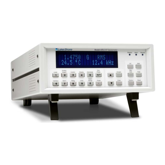
Model 475
DSP Gaussmeter
Lake Shore Cryotronics, Inc.
575 McCorkle Blvd.
Westerville, Ohio 43082-8888 USA
E-mail Addresses:
sales@lakeshore.com
service@lakeshore.com
Visit Our Website At:
www.lakeshore.com
Fax: (614) 891-1392
Telephone: (614) 891-2243
P/N 119-036
25 July 2017
Advertisement
Table of Contents
Troubleshooting

Related Manuals for Lake Shore 475


Summary of Contents for Lake Shore 475
- Page 1 Inc. in these developments. Methods and apparatus disclosed herein may be subject to U.S. Patents existing or applied for. Lake Shore Cryotronics, Inc. reserves the right to add, improve, modify, or withdraw functions, design modifications, or products at any time without notice. Lake Shore shall not be liable for errors contained herein or for incidental or consequential damages in connection with furnishing, performance, or use of this material.
- Page 2 "Warranty Period"). If Lake Shore receives notice of any such defects during the Warranty Period and the defective Product is shipped freight prepaid back to Lake Shore, Lake Shore will, at its option, either repair or replace the Product (if it is so defective) without charge for parts, service labor or associated customary return shipping cost to the Purchaser.
- Page 3 FIRMWARE LIMITATIONS Lake Shore has worked to ensure that the Model 475 firmware is as free of errors as possible, and that the results you obtain from the instrument are accurate and reliable. However, as with any computer-based software, the possibility of errors exists.
- Page 4 To qualify for the CE Mark, the Model 475 meets or exceeds the requirements of the European EMC Directive 89/336/EEC as a CLASS A product. A Class A product is allowed to radiate more RF than a Class B product and must include the...
-
Page 5: Eu Declaration Of Conformity
Lake Shore Model 475 Gaussmeter User’s Manual EU DECLARATION OF CONFORMITY This declaration of conformity is issued under the sole responsibility of the manufacturer. Manufacturer: Lake Shore Cryotronics, Inc. 575 McCorkle Boulevard Westerville, OH 43082 Object of the declaration: Model(s):... - Page 6 Lake Shore Model 475 Gaussmeter User’s Manual Copyright © 2003 – 2017 by Lake Shore Cryotronics, Inc. All rights reserved. No portion of this manual may be reproduced, stored in a retrieval system, or transmitted, in any form or by any means, electronic, mechanical,...
-
Page 7: Table Of Contents
Lake Shore Model 475 Gaussmeter User’s Manual TABLE OF CONTENTS Chapter/Section Title Page INTRODUCTION ........................1-1 GENERAL ..........................1-1 DESCRIPTION ........................1-1 1.1.1 Advanced Features ......................1-2 1.1.2 Measurement Features ....................... 1-3 1.1.3 Probe Support ........................1-3 1.1.4 Display and Interface Features ................... 1-4 SPECIFICATIONS ......................... - Page 8 Lake Shore Model 475 Gaussmeter User’s Manual TABLE OF CONTENTS Chapter/Paragraph Title Page OPERATION ..........................4-1 GENERAL ..........................4-1 TURNING POWER ON ......................4-1 DISPLAY DEFINITION ......................4-2 4.2.1 Display Units ........................4-2 4.2.2 Display and LED Annunciators ................... 4-2 KEYPAD DEFINITION ......................
- Page 9 Lake Shore Model 475 Gaussmeter User’s Manual TABLE OF CONTENTS Chapter/Paragraph Title Page ADVANCED OPERATION......................5-1 GENERAL ..........................5-1 PROBE MANAGEMENT ......................5-1 5.1.1 Clear Probe Zero Calibration ....................5-1 5.1.2 Probe Serial Number ......................5-1 5.1.3 Field and Temperature Compensation ................5-1 5.1.4...
- Page 10 7.5.1 Hall Generator Handling ...................... 7-7 7.5.2 Hall Generator Lead Wires ....................7-7 7.5.3 Using a Hall Generator with the Model 475 ................ 7-7 7.5.4 Attachment to A User Programmable Cable ............... 7-8 7.5.5 Hall Generator Specifications ....................7-8 HELMHOLTZ COIL LOW FIELD STANDARDS ..............7-9 REFERENCE MAGNETS .....................
-
Page 11: Introduction
The Model 475 is intended for the most demanding DC and AC applications and in many cases can provide the functions of two or more instruments in a field measurement system. The power of DSP technology is demonstrated in the superior performance of the Model 475 in DC, RMS, and Peak measurement modes. -
Page 12: Advanced Features
The gaussmeter can be configured to follow the peak of a periodic waveform for evaluation of crest factor. The Model 475 can also be used to sample field changes at 1000 readings per second that can later be read over interface to illustrate the shape of pulses or other waveforms. -
Page 13: Measurement Features
Keeping probes and their extensions from getting mixed up can become a problem when more than one probe is in use. The Model 475 alleviates some of the difficulty by allowing users to match probes to extensions in the field. -
Page 14: Display And Interface Features
This is by no means the limit of what is offered. All probe physical configurations previously supplied with the 450 gaussmeter are available for the Model 475. The model number for Model 475 probes is identical, except an “H”... -
Page 15: Specifications
Lake Shore Cryotronics, Inc. assumes no liability for Customer failure to comply with these requirements. The Model 475 protects the operator and surrounding area from electric shock or burn, mechanical hazards, excessive temperature, and spread of fire from the instrument. Environmental conditions outside of the conditions below may pose a hazard to the operator and surrounding area. -
Page 16: Safety Symbols
Lake Shore Model 475 Gaussmeter User’s Manual SAFETY SYMBOLS Introduction... -
Page 17: Background
This chapter provides background information related to the Model 475 Gaussmeter. It is intended to give the user insight into the benefits and limitations of the instrument and help apply the features of the Model 475 to a variety of experimental challenges. -
Page 18: Model 475 System Overview
This is referred to as the Nyquist frequency. In the case of the Model 475, the ADC is sampled at 40 kHz in wide band AC mode. -
Page 19: Dc Measurement
2.1.6 RMS Measurement The Model 475 offers two different modes of AC measurement, narrow-band and wide-band. In narrow-band AC measurement, the instrument uses a 100 mA, 5 kHz, square wave excitation current. This type of excitation provides the benefit of noise cancellation characteristics of the product detector but limits the maximum frequency to approximately 1 kHz. -
Page 20: Peak Measurement
Peak Measurement The Model 475 is capable of measuring the peak amplitudes of signals, either peak pulses or periodic pulses. In peak mode, the instrument uses a 100 mA, DC excitation current. The voltage that is generated by the Hall device is read by the A/D at 40 kHz. -
Page 21: Flux Density Overview
Lake Shore Model 475 Gaussmeter User’s Manual FLUX DENSITY OVERVIEW 2.2.1 What is Flux Density? A magnetic field can be envisioned as consisting of flux lines (φ). A unit of flux is called a line. In the cgs system, one line of flux equals one maxwell (Mx). -
Page 22: Active Area
Lake Shore Model 475 Gaussmeter User’s Manual The Hall voltage can be given by the expression: = γ B sin θ where: V = Hall voltage (mV) γ = Magnetic sensitivity (mV/kG) (at a fixed current) B = Magnetic field flux density (kilogauss) θ... -
Page 23: Orientation
To do this, it uses feedback from the probe to calculate and actively adjust the control (analog) output. The Model 475 uses a control algorithm called PI that refers to the two terms used to tune the controller for each unique system. -
Page 24: Proportional (P)
Manual Output The Model 475 has a control parameter that is not a normal part of a PI control loop. Manual output can be used for open loop control, meaning feedback is ignored and Analog Output 3 stays at the users manual setting. This is a good way to make the magnet power supply output a constant current. - Page 25 Lake Shore Model 475 Gaussmeter User’s Manual Figure 2-8. Examples of PI Control Background...
-
Page 26: Tuning A Closed Loop Pi Controller
Begin this part of the tuning process using the proportional setting found above. Enter an I setting of 100 to start with. If the field begins to oscillate, increase the I setting by a factor of two. Remember, in the Model 475, the integral term is set in seconds and a smaller setting creates a more active integrator. -
Page 27: Installation
Check off each item on the packing list as it is unpacked. Instruments themselves may be shipped as several parts. The items included with the Model 475 are listed below. Contact Lake Shore immediately if there is a shortage of parts or accessories. -
Page 28: Rear Panel Definition
Lake Shore Model 475 Gaussmeter User’s Manual REAR PANEL DEFINITION This paragraph defines the rear panel of the Model 475. See Figure 3-1. Readers are referred to paragraphs that contain installation instructions and connector pin-outs for each feature. A summary of connector pin-outs is provided in Paragraph 8.10. -
Page 29: Line Input Assembly
Line Fuse and Fuse Holder The line fuse is an important safety feature of the Model 475. If a fuse ever fails, it is important to replace it with the value and type indicated on the rear panel for the line voltage setting. The letter T on the fuse rating indicates that the instrument requires a time-delay or slow-blow fuse. -
Page 30: Probe Input Connection
Personal injury and damage to the instrument may result. The Lake Shore probe plugs into the 15 pin D-sub connector on the rear panel. Align the probe connector with the rear panel connector and push straight in to avoid bending the pins. For best results, secure the connector to the rear panel using the two thumbscrews. -
Page 31: Probe Operation
In the DC mode of operation, the orientation of the probe affects the polarity reading of the gaussmeter. On a transverse probe, the Lake Shore name printed on the handle indicates the side for positive (+) flux entry. On an axial probe, positive (+) flux entry is always from the front of the probe. -
Page 32: Probe Accuracy Considerations
Lake Shore Model 475 Gaussmeter User’s Manual 3.5.3 Probe Accuracy Considerations The user must consider all the possible contributors to the accuracy of the reading. Both the probe and gaussmeter have accuracy specifications that may impact the actual reading. The probe should be zeroed before making critical measurements. -
Page 33: Auxiliary I/O Connection
Refer to Paragraph 5.5 for trigger details. Relay1 and Relay 2: The Model 475 has two mechanical relays designated Relay 1 and Relay 2. The relays are most commonly associated with the high and low alarms, but they can also be controlled manually and used for other purposes. -
Page 34: Rack Mounting
Lake Shore Model 475 Gaussmeter User’s Manual RACK MOUNTING The Model 475 can be installed into a 19-inch rack mount cabinet using the optional Lake Shore Model RM½ Rack- Mount Kit, or the Model RM2 Dual Rack-Mount Shelf. The Rack-Mount Kit contains mounting ears, panel, handles, and screws that adapt the front panel to fit into a 3.5 inch tall, full rack space. - Page 35 Lake Shore Model 475 Gaussmeter User’s Manual Figure 3-8. Model RM2 Dual Rack-Mount Shelf (P/N 4026) Installation...
- Page 36 Lake Shore Model 475 Gaussmeter User’s Manual This Page Intentionally Left Blank 3-10 Installation...
-
Page 37: Operation
DSP Ga u s s me t e r When the Model 475 is turned on the display reads Lake Shore for a few seconds and the alarm beeper sounds briefly to indicate the instrument is initializing. Most instrument setup parameter values are retained when power is off with only a few exceptions. -
Page 38: Display Definition
Lake Shore Model 475 Gaussmeter User’s Manual DISPLAY DEFINITION In normal operation, the two row by twenty character vacuum fluorescent display provides readings defined by the selected measurement features on the top row, and special information or readings on the bottom row. The bottom row can be configured under most operating conditions (refer to Paragraph 4.4). -
Page 39: Keypad Definition
On steady when the alarm feature is on, blinks when the alarm is active . Indicates that the instrument is under remote control of the computer interface. Remote KEYPAD DEFINITION The Model 475 has 22 keys separated into 3 groups on the instrument front panel. 4.3.1 Key Descriptions Local... -
Page 40: General Keypad Operation
The user may configure the bottom row of the display. 4.4.1 Two-Line Display Configuration The Model 475 can be configured to display different values on the bottom line of the display. The following list gives a description of each setting. Blank No Bottom line display. -
Page 41: Display Brightness
Lake Shore Model 475 Gaussmeter User’s Manual 4.4.2 Display Brightness To change the brightness, press and hold the Display key for approximately 4 seconds. The display configuration screen appears as a prompt for display brightness. Operating continuously at 100% brightness will shorten the life of the display. -
Page 42: Dc Measurement Mode
To measure static or slowly changing fields, press the DC key on the front panel. In DC measurement mode, the keypad and functionality of the Model 475 is optimized to provide the best interaction for DC measurements. The keypad features are described in paragraphs 4.6.1 through 4.6.7. -
Page 43: Dc Operation Resolution And Filtering
DC Operation Resolution and Filtering The firmware linear filter is an integral part of the Model 475 DC measurement. It is directly related to measurement resolution, frequency response, and reading rate. The higher reading rates are only available over the computer interface, but the display will update at 5 readings per second independent of filter configuration. -
Page 44: Dc Operation Max Hold
Pr obe Of f s et Lar ger Th a n Ex p e c t e d The Model 475 will continue to operate with the offset correction, but it will be up to the individual to investigate the nature of the offset. - Page 45 Lake Shore Model 475 Gaussmeter User’s Manual Example: If the present maximum reading is +20 kG and the instrument measures –35 kG, the –35 kG becomes the new maximum reading. If the minimum reading is –3.0 kG and the instrument measures –1.5 kG, the –1.5 kG becomes the new minimum reading.
-
Page 46: Max/Min Display Setting
Lake Shore Model 475 Gaussmeter User’s Manual 4.6.4.2 Max/Min Display Setting Typically, the maximum reading (Max) is displayed on the top line when the Max Hold feature is on. Sometimes it may be beneficial to display the minimum reading (Min) on the top line instead of the maximum. The user may also display both the maximum and minimum readings, with the maximum reading on the top line and the minimum reading on the bottom line. -
Page 47: Dc Operation Analog Output 1 And 2
In the DC measurement mode, the signal available at Analog Output 1 may only be useful as a verification of the Model 475 measurement hardware. The signal contains the 5 kHz modulation of the current source making it difficult to use as an accurate field representation. -
Page 48: Rms Measurement Mode
4.7.1 through 4.7.8. Due to the flexibility of the filtering capability of the Model 475, the instrument communicates the present filter setting when entering RMS measurement mode. When the RMS key is pressed, the following message will appear for approximately 3 seconds. -
Page 49: Rms Operation Filter Selection
RMS Operation Filter Selection The Model 475 offers unique AC filtering capabilities to improve the overall RMS measurement performance. The instrument may be configured to use a DC current to excite the Hall sensor (Wide Band) or an AC current to excite the Hall sensor (Narrow Band or Lowpass). -
Page 50: Wide Band Filters
Lake Shore Model 475 Gaussmeter User’s Manual Figure 4-3. Wide Band and Narrow Band Filter 4.7.2.1 Wide Band Filters DC current excitation provides the greatest frequency range for RMS measurement. This frequency range is then divided into smaller sections by using the bandpass filters available in the Wide Band mode. The bandpass filters are specified by their center band frequency and are described in the following table. -
Page 51: Narrow Band Filters
Lowpass Filters The AC excitation is also used in the Lowpass filter configuration. This allows the Model 475 to measure its lowest frequency content and include the DC field component in the RMS reading if desired. Due to the long observation times required to measure low frequency AC fields, the RMS reading is valid to 1 Hz. - Page 52 Most RMS measurements reject the DC component of the measured field. This is the default configuration of the Model 475. If an application requires the inclusion of the DC, it can be turned on. The next screen appears as a prompt for rejecting the DC component.
-
Page 53: Rms Operation Frequency Measurement
RMS Operation Frequency Measurement With certain limitations, the Model 475 Gaussmeter is capable of measuring and displaying the frequency of an AC magnetic field. The frequency is calculated using a zero-crossing counter, so the indicated value is only valid for robust fields with a single, dominant frequency. -
Page 54: Rms Operation Max Hold
Lake Shore Model 475 Gaussmeter User’s Manual 4.7.5 RMS Operation Max Hold The Max Hold function captures the largest (Maximum) or smallest (Minimum) RMS field readings since the last Reset press. To turn the Max Hold feature on, press the Max Hold key. The following screen will appear for approximately 3 seconds. -
Page 55: Rms Operation Analog Output 1 And 2
±0.35 volts for full scale range. The output has a frequency range of 1 Hz to 50 kHz. If the Narrow Band or Lowpass filters are used, Analog Output 1 may only be useful as a verification of the Model 475 measurement hardware. -
Page 56: Peak Measurement Mode
To measure pulsed or periodic fields, press the Peak key on the front panel. In Peak measurement mode, the keypad and functionality of the Model 475 is optimized to provide the best interaction for Peak measurements. The keypad features are described in the following paragraphs. -
Page 57: Peak Operation Periodic/Pulse Setup
Lake Shore Model 475 Gaussmeter User’s Manual 4.8.2 Peak Operation Periodic/Pulse Setup The Peak measurement mode can be configured to measure pulsed fields or the maximum amplitude of periodic fields. In periodic mode, the instrument follows the peak amplitude of the periodic signal. This may be useful in determining additional information about AC fields, such as crest factor. -
Page 58: Peak Operation Relative
Lake Shore Model 475 Gaussmeter User’s Manual 4.8.6 Peak Operation Relative The relative function lets the user see small variations in larger fields. When the relative function is on, the relative readings will appear on the top line of the display including the small delta sign (s ) signifying the relative display. -
Page 59: Temperature Measurement
TEMPERATURE MEASUREMENT The Model 475 is capable of measuring the temperature of the probe, if the probe is equipped with a temperature sensor and a temperature compensation table. The probe temperature can be displayed as Kelvin or in degrees Celsius. Refer to Paragraph 4.4.1 for display setup. - Page 60 Lake Shore Model 475 Gaussmeter User’s Manual The alarm may be configured to use the magnitude of the field reading only (ignoring the sign), or to include the sign and treat the readings algebraically. To configure the alarm for magnitude or algebraic mode, press and hold the Alarm key for approximately 4 seconds.
- Page 61 Lake Shore Model 475 Gaussmeter User’s Manual The Model 475 has an audible alarm annunciator or beeper. The beeper will sound when the instrument is in an active alarm state. If the sound of the beeper is not appropriate for your application, it can be turned on or off by the user.
-
Page 62: 4.11 Relays
Press Escape to cancel the new selection and return to the normal display. The Model 475 can be configured to display pass or fail when it is used during repetitive magnet testing or sorting operations. The sort message can be turned on or off as necessary and does not affect other operations of the alarm feature. -
Page 63: Analog Output 3
Lake Shore Model 475 Gaussmeter User’s Manual The next relay setup screen appears as a prompt for operating mode. Sel ec t f or Rel 1 ° ® Re l a y 1 Use the s or t key to select the relay mode for manual operation (Off, On) or to follow the Alarm operation. Press Enter to accept the new selection and continue. - Page 64 Lake Shore Model 475 Gaussmeter User’s Manual 0 kG Display –3.5 kG –2.5 kG –1.5 kG +1.5 kG +2.5 kG +3.5 kG Reading Output –3.5 V –2.5 V –1.5 V +1.5 V +2.5 V +3.5 V Voltage If the User Defined mode is selected, the next analog setup screen appears as a prompt for the low setpoint value. This value represents the reading at which the Analog Output 3 will be -10 volts.
-
Page 65: Analog Output 3 Polarity
Press Escape again to cancel the sequence and return to the normal display. If the Control mode is selected, Analog Output 3 is configured to operate with the field control algorithm of the Model 475. Refer to the Control key description for configuring the field control parameters, Paragraph 5.2. 4.12.2... -
Page 66: 4.13 Locking The Keypad
Lake Shore Model 475 Gaussmeter User’s Manual 4.13 LOCKING THE KEYPAD The keypad lock feature prevents accidental changes to parameter values. When the keypad is locked all parameter values may be viewed but none may be changed from the front panel. - Page 67 Lake Shore Model 475 Gaussmeter User’s Manual The next screen appears as a prompt for returning the instrument parameters to default values. Default parameter values are listed in Table 4-1. Se l e c t W i t h ° ®...
- Page 68 Lake Shore Model 475 Gaussmeter User’s Manual This Page Intentionally Left Blank 4-32 Operation...
-
Page 69: Advanced Operation
Probe Serial Number The serial number of the probe presently attached can be viewed from the display of the Model 475. This feature can also be used to check the programming of extension cables. To view the serial number, press the Probe key. The following screen will appear for approximately 6 seconds. -
Page 70: Extension Cable
Keeping probes and their extensions from getting mixed up can become a problem when more than one probe is in use. The Model 475 alleviates some of the difficulty by allowing users to match probes to extensions in the field. -
Page 71: Hall Generator
Lake Shore Model 475 Gaussmeter User’s Manual Visually verify that a valid HMPEC cable is attached to the Model 475. Press Enter to copy the probe characteristics to the memory of the extension cable. Press Escape to cancel the process and return to the normal display. - Page 72 The next MCBL program screen appears as a prompt for entering the nominal sensitivity in mV/kG. This sensitivity is based on the control current to be used (1 mA, 10 mA, or 100 mA). Note that the sensitivity of Lake Shore Hall sensors is specified at 100 mA in most cases.
-
Page 73: Ohms Measurement Mode
Ohms Measurement Mode The Model 475 may be configured to make a 4-lead resistive measurement. If the sensitivity of the probe is set to 0, the instrument will read in ohms. Instrument features are limited in this mode. The following ranges are available in this mode: 350 µΩ, 3.5 mΩ, 35 mΩ, 350 mΩ, 3.5 Ω, 35 Ω, and 350 Ω. -
Page 74: P And I Settings
Control Setpoint Ramp Rate The Model 475 can also be configured to ramp the control setpoint from the present field reading to a new value. The ramp may allow a smooth linear transition in field rather than the typical step response associated with Closed Loop PI control. -
Page 75: Control Slope Limit
Control Slope Limit The Model 475 Analog Output 3 (used during control) can be limited to protect the programmable power supply that it may be driving. Certain power supplies may have a maximum programmable voltage change, and this parameter will allow those specifications to be met. -
Page 76: Triggering
The hardware trigger input is an edge sensitive, active low signal. To ensure that the trigger is detected by the Model 475, it is recommended that the signal be held high for a minimum of 25 microseconds, and then held low for another 25 microseconds before going high again. -
Page 77: Computer Interface Operation
4005) is required to use the IEEE-488 Interface and the Auxiliary connector at the same time. Cable lengths are limited to 2 meters for each device and 20 meters for the entire bus. The Model 475 can drive a bus with up to 10 loads. -
Page 78: Changing Ieee-488 Interface Parameters
6.1.2 Remote/Local Operation Normal operations from the keypad are referred to as ‘Local’ operations. The Model 475 can also be configured for ‘Remote’ operations via the IEEE-488 interface or the Local key. The Local key will toggle between ‘Remote’ and ‘Local’... -
Page 79: Common Commands
IEEE-488 1987 standard share these commands and their format. Common commands all begin with an asterisk. They generally relate to “bus” and “instrument” status and identification. Common query commands end with a question mark (?). Model 475 common commands are detailed in Paragraph 6.3 and summarized in Table 6-9. -
Page 80: Highspeed Binary Output Configuration
High Speed Binary Output Configuration The Model 475 is capable of sending field readings over the IEEE interface at a rate of 100 readings per second. For this to be possible, the data is sent in the IEEE-754 floating point format. This reduces the overhead of sending the data in an ASCII format. -
Page 81: Status System
6.1.4.1 Overview The Model 475 implements a status system compliant to the IEEE 488.2 – 1992 standard. The status system provides a method of recording and reporting instrument information and is typically used to control the Service Request (SRQ) interrupt line. A diagram of the status system is shown in Figure 6-2. The status system is made up of register sets, the Status Byte register, and the Service Request Enable register. - Page 82 Lake Shore Model 475 Gaussmeter User’s Manual Figure 6-2. Model 475 Status System Remote Operation...
- Page 83 Lake Shore Model 475 Gaussmeter User’s Manual 6.1.4.1.5 Reading Registers Any register in the status system may be read using the appropriate query command. Some registers clear when read, others do not. Refer to Paragraph 6.1.4.1.7. The response to a query will be a decimal value which corresponds to the binary-weighted sum of all bits in the register, refer to Table 6-1.
-
Page 84: Status Register Sets
Lake Shore Model 475 Gaussmeter User’s Manual 6.1.4.2 Status Register Sets As shown in Figure 6-2, there are two register sets in the status system of the Model 475: Standard Event Status Register and Operation Event Register. 6.1.4.2.1 Standard Event Status Register Set The Standard Event Status Register reports the following interface related instrument events: power on detected, command syntax errors, command execution errors, query errors, operation complete. -
Page 85: Status Byte And Service Request (Srq)
Lake Shore Model 475 Gaussmeter User’s Manual Figure 6-4. Operation Event Register 6.1.4.3 Status Byte and Service Request (SRQ) As shown in Figure 6-2, the Status Byte Register receives the summary bits from the two status register sets and the message available summary bit from the output buffer. - Page 86 Lake Shore Model 475 Gaussmeter User’s Manual 6.1.4.3.2 Service Request Enable Register The Service Request Enable Register is programmed by the user and determines which summary bits of the Status Byte may set bit 6 (RQS/MSS) to generate a Service Request. Enable bits are logically ANDed with the corresponding summary bits, see Figure 6-5.
- Page 87 The bus controller can, for example, send a query command to the Model 475 and then wait for MAV to set. If the MAV bit has been enabled to initiate an SRQ, the user’s program can direct the bus controller to look for the SRQ leaving the bus available for other use.
-
Page 88: Ieee Interface Example Programs
Lake Shore Model 475 Gaussmeter User’s Manual 6.1.5 IEEE Interface Example Program A Visual Basic program is included to illustrate the IEEE-488 communication functions of the instrument. Refer to Paragraph 6.1.5.1 for instructions on how to setup the program. The Visual Basic code is provided in Table 6-5. A description of program operation is provided in Paragraph 6.1.5.3. - Page 89 Lake Shore Model 475 Gaussmeter User’s Manual Figure 6-6. GPIB0 Setting Configuration Figure 6-7. DEV 12 Device Template Configuration Remote Operation 6-13...
-
Page 90: Visual Basic Ieee-488 Interface Program Setup
Lake Shore Model 475 Gaussmeter User’s Manual 6.1.5.2 Visual Basic IEEE-488 Interface Program Setup This IEEE-488 interface program works with Visual Basic 6.0 (VB6) on an IBM PC (or compatible) with a Pentium- class processor. A Pentium 90 or higher is recommended, running Windows 95 or better. It assumes your IEEE-488 (GPIB) card is installed and operating correctly (refer to Paragraph 6.1.5.1). - Page 91 Lake Shore Model 475 Gaussmeter User’s Manual Table 6-4. IEEE-488 Interface Program Control Properties Current Name Property New Value Label1 Name lblExitProgram Caption Type “exit” to end program. Label2 Name lblCommand Caption Command Label3 Name lblResponse Caption Response Text1 Name...
- Page 92 Lake Shore Model 475 Gaussmeter User’s Manual Table 6-5. Visual Basic IEEE-488 Interface Program Public gSend As Boolean 'Global used for Send button state Private Sub cmdSend_Click() 'Routine to handle Send button press gSend = True 'Set Flag to True...
-
Page 93: Program Operation
Lake Shore Model 475 Gaussmeter User’s Manual 6.1.5.3 Program Operation Once either example program is running, try the following commands and observe the response of the instrument. Input from the user is shown in bold and terminators are added by the program. The word [term] indicates the required terminators included with the response. -
Page 94: Serial Interface Overview
SERIAL INTERFACE OVERVIEW The serial interface used in the Model 475 is commonly referred to as an RS-232C interface. RS-232C is a standard of the Electronics Industries Association (EIA) that describes one of the most common interfaces between computers and electronic equipment. -
Page 95: Hardware Support
Hardware Support The Model 475 interface hardware supports the following features. Asynchronous timing is used for the individual bit data within a character. This timing requires start and stop bits as part of each character so the transmitter and receiver can resynchronized between each character. -
Page 96: Message Flow Control
Lake Shore Model 475 Gaussmeter User’s Manual Message Strings (Continued) A query string is issued by the computer and instructs the instrument to send a response. The query format is: <query mnemonic><?><space><parameter data><terminators>. Query mnemonics are often the same as commands with the addition of a question mark. Parameter data is often unnecessary when sending queries. -
Page 97: Visual Basic Serial Interface Program Setup
Lake Shore Model 475 Gaussmeter User’s Manual 6.2.7.1 Visual Basic Serial Interface Program Setup The serial interface program works with Visual Basic 6.0 (VB6) on an IBM PC (or compatible) with a Pentium-class processor. A Pentium 90 or higher is recommended, running Windows 95 or better, with a serial interface. It uses the COM1 communications port at 9600 Baud. - Page 98 Lake Shore Model 475 Gaussmeter User’s Manual Table 6-7. Serial Interface Program Control Properties Current Name Property New Value Label1 Name lblExitProgram Caption Type “exit” to end program. Label2 Name lblCommand Caption Command Label3 Name lblResponse Caption Response Text1 Name...
- Page 99 Lake Shore Model 475 Gaussmeter User’s Manual Table 6-8. Visual Basic Serial Interface Program Public gSend As Boolean 'Global used for Send button state Private Sub cmdSend_Click() 'Routine to handle Send button press gSend = True 'Set Flag to True...
-
Page 100: Program Operation
Lake Shore Model 475 Gaussmeter User’s Manual 6.2.7.2 Program Operation Once either example program is running, try the following commands and observe the response of the instrument. Input from the user is shown in bold and terminators are added by the program. The word [term] indicates the required terminators included with the response. -
Page 101: Command Summary
Lake Shore Model 475 Gaussmeter User’s Manual COMMAND SUMMARY This paragraph provides a listing of the IEEE-488 and Serial Interface Commands. A summary of all the commands is provided in Table 6-9. All the commands are detailed in Paragraph 6.3.1, presented in alphabetical order. - Page 102 Lake Shore Model 475 Gaussmeter User’s Manual Table 6-9. Command Summary Command Function Page Command Function Page LOCK Front Panel Keyboard Lock Cmd......6-34 Clear Interface Cmd ..........6-27 LOCK? Front Panel Keyboard Lock Query ..... 6-34 Standard Event Status Enable Register Cmd ..6-27 MXHOLD Max Hold Cmd ...........
-
Page 103: Interface Commands (Alphabetical Listing)
Lake Shore Model 475 Gaussmeter User’s Manual 6.3.1 Interface Commands (Alphabetical Listing) *CLS Clear Interface Command Input: *CLS [term] Remarks: Clears the bits in the Standard Event Status Register and Operation Event Register and terminates all pending operations. Clears the interface, but not the instrument. The related instrument command is *RST. - Page 104 *TST? [term] Returned: <status>[term] Format: <status> 0 = No errors found, 1 = Errors found Remarks: The Model 475 reports status based on test done at power up. *WAI Wait-to-Continue Command Input: *WAI [term] Remarks: This command is not supported in the Model 475.
- Page 105 Lake Shore Model 475 Gaussmeter User’s Manual ALARM Alarm Parameter Command Input: ALARM <off/on>, <mode>, <low value>, <high value>, <out/in>, <sort>[term] Format: n,n,±nnn.nnnE±nn,±nnn.nnnE±nn,n,n <off/on> Specifies alarm checking on or off: 0 = Off, 1 = On. <mode> Specifies checking magnitude(absolute value used) or algebraically(includes sign): 1 = Magnitude check, 2 = Algebraic check.
- Page 106 Lake Shore Model 475 Gaussmeter User’s Manual ANALOG? Analog Output 3 Parameter Query Input: ANALOG? [term] Returned: <mode>, <polarity>, <low value>, <high value>, <manual value>, <voltage limit> [term] Format: n,n,±nnn.nnnE±nn,±nnn.nnnE±nn,±nnn.nnnE±nn (Refer to command for definition) AOUT? Analog Output 3 Data Query...
- Page 107 Lake Shore Model 475 Gaussmeter User’s Manual BRIGT? Display Brightness Query Input: BRIGT? [term] Returned: <bright>[term] Format: (Refer to command for description) CMODE Field Control Mode Command Input: CMODE <mode>[term] Format: <mode> Specifies the control mode. Valid entries: 0 = Off, 1 = Closed Loop PI.
- Page 108 6 = Alarm Sort message Example: DISPLAY 3[term] – Probe Temperature will be displayed on Line 2 if the probe is capable of measuring temperature. The Frequency will also be displayed if the Model 475 is in RMS mode. DISPLAY? Display Configuration Query...
- Page 109 Lake Shore Model 475 Gaussmeter User’s Manual DLOGSET Datalog Rate Command Input: DLOGSET <rate> [term] Format: <rate> Configures the Datalog readings per second: 1 = 1 reading per second 2 = 10 readings per second 3 = 30 readings per second...
- Page 110 Minimum on bottom line. This overrides the DISPLAY command configuration. Example: MXHOLD 1,1,2[term] – Turns the Max Hold feature on using the Magnitude checking mode. The Model 475 displays both Max and Min values. MXHOLD? Max Hold Query Input: MODE? [term] Returned: <off/on>,<mode>,<display>...
- Page 111 MODE <mode>[term] Format: <mode> 0 = local, 1 = remote, 2 = remote with local lockout. Example: MODE 2[term] – Places the Model 475 into remote mode with local lockout. MODE? Remote Interface Mode Query Input: MODE? [term] Returned: <mode>[term]...
- Page 112 Lake Shore Model 475 Gaussmeter User’s Manual PRBFCOMP Probe Field Compensation Command Input: PRBFCOMP <off/on>[term] Format: <off/on> Specifies Probe Field compensation off or on. Valid entries: 0 = off, 1 = on. Example: PRBFCOMP 1[term] – Field Measurement uses the Probe Field Compensation table...
- Page 113 Example: RDGMODE 1,3,1,1,1[term] – The Model 475 is configured for DC field measurement, dc resolution of 5 digits, wide band rms filter mode, peak measurement mode is periodic, and positive peak readings will be displayed if the measurement mode is changed to peak.
- Page 114 Lake Shore Model 475 Gaussmeter User’s Manual RDGMNMX? Minimum and Maximum Reading Query Input: RDGMNMX? [term] Returned: <min>,<max>[term] ±nnn.nnnE±nn, ±nnn.nnnE±nn Format: Remarks: Returns the most recent minimum and maximum field readings. RDGOHM? Resistance Reading Query Input: RDGOHM? [term] Returned: <hall resistance>[term] ±nnn.nnnE±nn...
- Page 115 Lake Shore Model 475 Gaussmeter User’s Manual RELAY Relay Parameter Command Input: RELAY <relay number>, <mode>, <alarm type>[term] Format: n,n,nn,n <relay number> Specifies which relay to configure: 1 = Relay 1, 2 = Relay 2. <mode> Specifies relay mode: 0 = Off, 1 = On, 2 = Alarms.
- Page 116 Probe Temperature Units Command Input: TUNIT <units>[term] Format: <units> 1 = Celsius, 2 = Kelvin Example: TUNIT 1[term] – Configures the Model 475 to report probe temperature in °C. TUNIT? Probe Temperature Units Query Input: TUNIT? [term] Returned: <units>[term] Format:...
-
Page 117: Probes And Accessories
Half-Rack Mounting Kit for One 1/2 Rack Gaussmeter. Half-length mounting panel and mounting RM-1/2 ears to attach one Model 475 to a 483 mm (19-inch) rack mount space. See Figure 3-7. Dual Mounting Shelf for Two 1/2 Rack Gaussmeters. Mounting panel and mounting ears to attach RM-2 two Model 475 DSP Gaussmeters to a 483 mm (19-inch) rack mount space. -
Page 118: Lake Shore Standard Probes
There are several types of Lake Shore Model 475 probes available: Axial, Gamma, Tangential, and Transverse — generally named for the Hall sensor orientation. Because the Model 475 covers such a wide magnetic field range (0.01 mG to 350 kG), three probe ranges are available: High Stability (HST), High Sensitivity (HSE), and Ultra-High Sensitivity (UHS). - Page 119 Multi-axis probes are available for multi-axis gaussmeters like the Lake Shore Model 460. These probes are not compatible with the Model 475. Frequency: Hall-effect gaussmeters, like the Model 475, are equally well suited for measuring either static, DC fields or periodic, AC fields but proper probe selection is required to get optimal performance.
-
Page 120: Radiation Effects On Gaussmeter Probes
Lake Shore Model 475 Gaussmeter User’s Manual 7.3.2 Radiation Effects on Gaussmeter Probes The HST and HSE probes use a highly doped indium arsenide active material. The HST material is the more highly doped of the two and therefore will be less affected by radiation. Some general information relating to highly doped indium arsenide Hall generators is as follows: •... -
Page 121: Probe Specifications
Hall Generator Cable Assembly. The HMCBL Cable Assembly connects a discrete Hall generator to the Model 475 Gaussmeter. Refer to Paragraph 7.5. Because of the many calibration intricacies, the user is responsible for measurement accuracy. Refer to Paragraph 5.2 for programming HMCBL-XX instructions. - Page 122 Lake Shore Model 475 Gaussmeter User’s Manual Reference Magnets. High-quality reference magnets are available in transverse (flat) and axial (round) configurations. Refer to Paragraph 7.7 and see Figure 7-16. MRA-312-100 Axial Reference Magnet: 0.312 inch inside diameter, 100 G, 1% MRA-312-200 Axial Reference Magnet: 0.312 inch inside diameter, 200 G, 1%...
-
Page 123: Hall Generator
Manganin wire is not usually acceptable for connection to a Hall generator because the resistance of Manganin wire is often too high. The gaussmeter current source is limited in compliance voltage. The Model 475 should not drive a load (Hall generator, wires in cryostat, and probe cable) greater than 50 Ω. In fact, for best performance, the load should be less than 30 Ω. -
Page 124: Attachment To A User Programmable Cable
The Model HMCBL-XX has a 15 pin D-sub connector on one end for direct attachment to the PROBE INPUT connection on the back panel of the Model 475 Gaussmeter. Four tinned wires are provided for connection to the Hall Generator. The leads may be soldered directly to these wires. The cable comes in two lengths: the HMCBL-6 is 2 meters (6 feet) and the HMCBL-20 is 6 meters (20 feet). -
Page 125: Helmholtz Coil Low Field Standards
Lake Shore Model 475 Gaussmeter User’s Manual HELMHOLTZ COIL LOW FIELD STANDARDS Lake Shore offers three Helmholtz coils: 2.5-, 6-, and 12-inch diameter. Check the Lake Shore website for any recent additions to this line. These coils are accurately calibrated using field standards maintained at Lake Shore. Most standards are traceable to physical standards such as a coil of carefully controlled dimensions, or in some cases, to proton resonance. - Page 126 Lake Shore Model 475 Gaussmeter User’s Manual Helmholtz_6.bmp Figure 7-14. Model MH-6 Helmholtz Coil Helmholtz_12.bmp Figure 7-15. Model MH-12 Helmholtz Coil 7-10 Probes and Accessories...
-
Page 127: Reference Magnets
Lake Shore Model 475 Gaussmeter User’s Manual REFERENCE MAGNETS Magnetic reference standards containing highly stable permanent magnets have been in use for many years. The highest quality units are usually shielded from external magnetic effects and use Alnico V or VI magnets for long-term stability. -
Page 128: Zero Gauss Chamber
Lake Shore Model 475 Gaussmeter User’s Manual ZERO GAUSS CHAMBER NOTE: Use care to ensure the Zero Gauss Chamber does not become magnetized. Using a magnetized chamber to zero a probe can lead to erroneous field readings. It is a good practice to periodically degauss the chamber. -
Page 129: Service
CONTACTING LAKE SHORE CRYOTRONICS If a Lake Shore product was purchased through a dealer or representative, please use that resource for prompt sales or service information. When contacting Lake Shore directly, please specify the name of a department if do not know the name of an individual. -
Page 130: Fuse Drawer
FUSE DRAWER The fuse drawer supplied with the Model 475 holds the instrument line fuses and line voltage selection module. The drawer holds two 5 × 20 mm time delay fuses. It requires two good fuses of the same rating to operate safely. -
Page 131: Error Messages
Measurement No Probe There is no probe attached or the attached probe is damaged. The detected probe is not recognized as a valid Model 475 probe. Press Enter to Invalid Probe continue. A previous generation probe has been attached. Press Enter to continue. Measurement Incompatible Probe uses only nominal probe sensitivity. -
Page 132: Electrostatic Discharge
Lake Shore Model 475 Gaussmeter User’s Manual ELECTROSTATIC DISCHARGE Electrostatic Discharge (ESD) may damage electronic parts, assemblies, and equipment. ESD is a transfer of electrostatic charge between bodies at different electrostatic potentials caused by direct contact or induced by an electrostatic field. -
Page 133: Enclosure Top Removal And Replacement
Lake Shore Model 475 Gaussmeter User’s Manual ENCLOSURE TOP REMOVAL AND REPLACEMENT WARNING: To avoid potentially lethal shocks, turn off controller and disconnect it from AC power line before performing this procedure. Only qualified personnel should perform this procedure. REMOVAL Set power switch to Off (O) and disconnect power cord from rear of unit. - Page 134 Lake Shore Model 475 Gaussmeter User’s Manual PCB Layout.bmp Figure 8-3. Location of Important Internal Components Service...
-
Page 135: 8.10 Connector And Cable Definitions
Lake Shore Model 475 Gaussmeter User’s Manual Firmware Replacement (Continued) CAUTION: The ICs are Electrostatic Discharge Sensitive (ESDS) devices. Wear shock-proof wrist straps (resistor limited to <5 mA) to prevent injury to service personnel and to avoid inducing an Electrostatic Discharge (ESD) into the device. - Page 136 Lake Shore Model 475 Gaussmeter User’s Manual Probe_Input.bmp Description Description V input + V input – No Connection No Connection V temp + EEPROM GND I temp + EEPROM VCC I temp – EEPROM CLK V temp – EEPROM DATA No Connection I hall –...
-
Page 137: Serial Interface Cable Wiring
7 - DTR (tied to 4) 8 - CTS (in) 8 - NC 7 - RTS (out) 9 - NC 9 - NC NOTE: Same as null modem cable design except PC CTS is provided from the Model 475 on DTR. Service... -
Page 138: Ieee-488 Interface Connector
The total length of cable allowed in a system is 2 meters for each device on the bus, or 20 meters maximum. The Model 475 can drive a bus of up to 10 devices. A connector extender is required to use the IEEE-488 Interface and the Auxiliary I/O connector at the same time. -
Page 139: 8.11 Calibration Procedure
Gaussmeter Calibration The Model 475 is calibrated against a set of standard resistors. The Model 475 is configured to give readings in ohms. The highest range for the 100 mA excitation current is calibrated by measuring the 3 Ω standard resistor. This resistor is measured by using the HP 3458 to measure the current source of the 475 and the voltage across the resistor. -
Page 140: Gaussmeter Calibration, 10 Ma Excitation Ranges
This section describes the method of calibrating the 10 mA current source that may be used for future Hall sensors. The five ranges of the 475 will need to be calibrated for each current setting. The highest range is for each current is calibrated using a 33.2 Ω... -
Page 141: Gaussmeter Calibration, 1Ma Excitation Ranges
This section describes the method of calibrating the 1 mA current source that may be used for future Hall sensors. The five ranges of the 475 will need to be calibrated for each current setting. The highest range is for each current is calibrated using a 332 Ω... -
Page 142: Temperature Measurement Calibration
Model 475. These values are to be used whenever the outputs are accessed. The gain and offset values should also be checked to assure that they are reasonable in value and reject them if they fall outside a given range. -
Page 143: Analog Output 3 Calibration
Full Scale. Test this factor to be between -1 and 1. Record this value. 12. Send the Offset Correction Factor (OCF) to the Model 475 (CALZ 4,3,<OCF>). 13. Configure Analog Output 3 to manual mode, -100% (ANALOG 3,2,0,0,-100,10). -
Page 144: Calibration Specific Interface Commands
Lake Shore Model 475 Gaussmeter User’s Manual 8.11.5 Calibration Specific Interface Commands CALG Gain Calibration Constant Command Input: CALG <type>, <range>, <value>[term] Format: n,n,±nnnnnnn <type> Specifies the item to calibrate. Valid entries are: 1 = 100 mA hall current source... - Page 145 Lake Shore Model 475 Gaussmeter User’s Manual CALZ Zero Offset Calibration Constant Command Input: CALZ <type>, <range>, <value>[term] Format: n,n,±nnnnnnn <type> Specifies the item to calibrate. Valid entries are: 1 = 100 mA hall current source (not used) 2 = 10 mA hall current source (not used)
- Page 146 Lake Shore Model 475 Gaussmeter User’s Manual HALLCS Hall Current Source Range Command Input: HALLCS <range>[term] Format: <range> Specifies the hall current source range. Valid entries are: 1 = 100 mA range 2 = 10 mA range 3 = 1 mA range...
-
Page 147: Units For Magnetic Properties
Lake Shore Model 475 Gaussmeter User’s Manual APPENDIX A UNITS FOR MAGNETIC PROPERTIES Table A-1. Conversion from CGS to SI Units Gaussian Conversion SI & Quantity Symbol Rationalized mks & CGS emu Factor, C Magnetic flux density, tesla (T), Wb/m –4... - Page 148 Lake Shore Model 475 Gaussmeter User’s Manual Table A-2. Recommended SI Values for Physical Constants Quantity Symbol Value (SI units) µ Permeability of Vacuum –7 –1 4π × 10 –1 Speed of Light in Vacuum 2.9979 × 10 ε –12 –1...
Need help?
Do you have a question about the 475 and is the answer not in the manual?
Questions and answers