Table of Contents
Advertisement
Advertisement
Table of Contents

Subscribe to Our Youtube Channel
Related Manuals for VTS Medical Systems HMI-WING EC

Summary of Contents for VTS Medical Systems HMI-WING EC
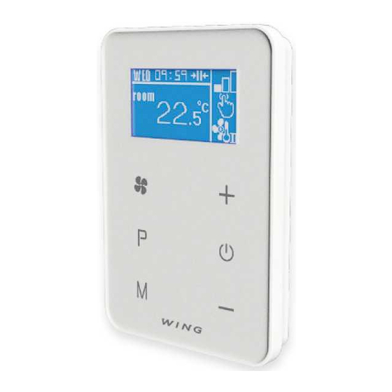
- Page 1 Device Integration Manual on Modbus RTU Bus Ver. 1.3...
- Page 2 fffffffff 1. Outputs 1. Outputs Picture 1: device outputs View Picture 1: device outputs View Terminal block Terminal block Terminal block L - 230 VAC Analogue output Analogue output B - RS 485Line N - 230 VAC mass Heating level 1 A - RS 485 Line Door sensor Heating level 2...
- Page 3 2. Device-operated functions Function code Description 0x01 Binary output status read 0x02 Binary input status read 0x03 Memory register read 0x04 Input register read 0x05 Record of one binary output 0x06 Record of one memory register 0x0F Record of many binary outputs 0x10 Record of many memory registers Table 2: Device-operated functions.
- Page 4 Binary output status read (code 2) - Function allows, with one message, to read many subsequent addressed binary output statuses. The attempt to read an non-existing binary input leads to error message Example: 1-5 output read Request Response Field name Field name Function code 0x02...
- Page 5 Input Register Read (code 4) – the Function allows, with one message, to read subsequently addressed registers . An attempt to read a non-existing register leads to an error message. Example: Register 9 read Request Response Field name Field name Function code 0x04 Function code...
- Page 6 Register value - high part 0x00 Register value - high part 0x00 Register value - low part 0x03 Register value - low part 0x03 Table 10: Exemplery record of one memory register Record of many binary outputs (code 15) - Function that allows, with one message, to record many subsequently addressed binary outputs.
- Page 7 Register address - low part 0xFF Register address - low part 0xFF Number of registers – high part Number of registers – high part 0x00 0x00 Number of registers – low part Number of registers – low part 0x02 0x02 Bytes 0x04 Register value - high part (256)
-
Page 8: Table Of Contents
3. Data blocks used by the device 2.1. Memory registers Address Default Variable For PDU value MB_ADDR_BAUDRATE * 0x0000 MB_ADDR_PARITY_MODE * 0x0001 MB_ADDR_SLAVE_ADDR * 0x0002 MB_ADDR_NTC_1_CORRECT * 0x0003 MB_ADDR_NTC_PERIOD 0x0004 MB_ADDR_RTC_WEEK_DAY 0x0005 MB_ADDR_RTC_YEAR 0x0006 MB_ADDR_RTC_MONTH 0x0007 MB_ADDR_RTC_DAY 0x0008 MB_ADDR_RTC_HOUR 0x0009 MB_ADDR_RTC_MINUTE 0x000A MB_ADDR_RTC_SECOND... - Page 9 MB_ADDR_ZONE_SCHEDULE_MON_FRI_WORK_1_STOP 0x001C MB_ADDR_ZONE_SCHEDULE_MON_FRI_WORK_2_START 0x001D MB_ADDR_ZONE_SCHEDULE_MON_FRI_WORK_2_STOP 0x001E 1080 MB_ADDR_ZONE_SCHEDULE_SAT_WORK_1_START 0x001F MB_ADDR_ZONE_SCHEDULE_SAT_WORK_1_STOP 0x0020 MB_ADDR_ZONE_SCHEDULE_SAT_WORK_2_START 0x0021 MB_ADDR_ZONE_SCHEDULE_SAT_WORK_2_STOP 0x0022 1080 MB_ADDR_ZONE_SCHEDULE_SUN_WORK_1_START 0x0023 MB_ADDR_ZONE_SCHEDULE_SUN_WORK_1_STOP 0x0024 MB_ADDR_ZONE_SCHEDULE_SUN_WORK_2_START 0x0025 MB_ADDR_ZONE_SCHEDULE_SUN_WORK_2_STOP 0x0026 1080 *registers of single record (one message must include a record of only one register) Table 14: Memory register type data block organization. Caution !!! Recording registers with addresses from 0 to 3 must contain a record of only one variable.
-
Page 10: Mb_Addr_Slave_Addr
EEPROM memory, and the device reset procedurę will be triggered MB_ADDR_SLAVE_ADDR - address of the device on MODBUS bus. Allowed values for variable within a range from 1 to 247. Attempt to record other number will lead to an error message. Upon sending a correct value, other than the current one, new address will be recorded in the backed-up EEPROM memory, and the device reset procedure will be triggered MB_ADDR_NTC_1_CORRECT - Register allowing setting the correction value for temperatures... -
Page 11: Mb_Addr_Rtc_Month
MB_ADDR_RTC_YEAR - a variable that determines a currently set year. Allowable values for the variable fall within a range from 0 to 99. Attempt to record a number beyond allowable values leads to an error message. MB_ADDR_RTC_MONTH - a variable that determines currently set month. Allowable values for the variable fall within a range from 1 to 12. - Page 12 = (MB_ADDR_FAN_POWER_2_VOLT / 100)[V]. SPEED MB_ADDR_FAN_POWER_3_VOLT - a variable that determines a voltage value that will be exposed to the analogue output connected with a fan for a third gear. Recording in this register is locked = (MB_ADDR_FAN_POWER_3_VOLT / 100)[V]. SPEED MB_ADDR_FAN_ADDITIONAL_VOLT - a variable that allows to set an additional constant value added to the voltage exposed to the analogue output assigned to the fan.
- Page 13 MB_ADDR_ZONE_PROGRAM - a variable that allows to set a operating mode of the device. Acceptable values for the variable: Variable Operating mode Descritpion value Continuous Constant (not time-limited) control of room atmosphere Environment control in rooms dependent on schedule (see from MB ADDR Schedule ZONE SCHEDULE...
-
Page 14: Mb_Addr_Fan_Power_1_Volt
Characteristics Operat Variable value mode Heater Target temperature Depedning on value of supply MB_ADDR_FAN_SPEED Heating MB ADDR ZONE TEMPER one output is set to the ATURE_TARGET heater ( terminal block J1-H) Heating MB ADDR ZONE TEMPER Two outputs are set for ATURE_TARGET the heater (J1-H1+H2 terminal block) -
Page 15: Mb_Addr_Zone_Temperature_Delta
MB_ADDR_ZONE_TEMPERATURE_TARGET - A variable that determines a currently set target temperature. Allowable values variable fall within range from MB_ADDR_ZONE_TEMPERATURE_MIN to MB_ADDR_ZONE_TEMPERATURE_MAX. Attempt to record a number beyond the allowable values leads to an error message. The variable is stored in backed-up EEPROM memory. -
Page 16: Mb_Addr_Zone_Schedule_Mon_Fri_Work_1_Start
Caution !!! • Values recorded in the register are rounded to 0.5[°C].. E.g. sending a number equal to 2254 (22.54[°C]) to the register leads to setting a value of 2250 (22.50[°C]). • Should the recorded value of the minimal temperature be lower than currently set target temperature (MB_ADDR_ZONE_TEMPERATURE_TARGET), the value of target temperature will be overwritten by the maximal temperature value . -
Page 17: Mb_Addr_Zone_Schedule_Mon_Fri_Work_2_Stop
Caution !!! • Values recorded in the register are rounded to 15[min]. E.g. sending a number equal to 905(15:05) to the register will lead to set the value equal to 900 (15:00) • The value in MB_ADDR_ZONE_SCHEDULE_MON_FRI_WORK_2_START must be lower than the value in MB ADDR ZONE SCHEDULE MON FRI WORK 2 STOP. -
Page 18: Mb_Addr_Zone_Schedule_Sat_Work_2_Start
• The value in MB_ADDR_ZONE_SCHEDULE_SAT_WORK_1_STOP must be higher than the value in MB_ADDR_ZONE_SCHEDULE_SAT_WORK_1_START. MB AD DR ZONE SCHEDULE SAT WORK 2 ST ART - - allows to set a date of commencement of second daily heating period for Saturday. Allowable values for the variable fall within a range from 0 to 1425 (00:00 to 23:45). -
Page 19: Mb_Addr_Zone_Schedule_Sun_Work_1_Stop
MB_ADDR_ZONE_SCHEDULE_SUN_WORK_1_STOP - allows to set a date of end of first daily heating period for Sunday. Allowable values for the variable fall within a range from 0 to 1425 (00:00 to 23:45). Attempt to record a number beyond the allowable values leads to an error message. The variable is stored in backed-up EEPROM memory. - Page 20 2.2. Input registers Address Default Variable For PDU value MB_ADDR_ZONE_TEMPERATURE_ACTUAL 0x0000 MB_ADDR_ZONE_ACTUAL_PROGRAM_STATE 0x0001 Table 22: input register type data block organization MB_ADDR_ZONE_TEMPERATURE_ACTUAL - register that contains information on current temperature of a room in which the device is located. As a result of the register read, the vaue is obtained, from which the temperature is determined through the following formula: T measured = ( MB_ADDR_ZONE_TEMPERATURE_ACTUAL / 100)[°C] Caution !! In case of damage to the sensor, the value obtained due to read, will equal to -32768,...
- Page 21 2.3. Binary inputs Address Default Variable For PDU value MB_ADDR_INPUT_1 0x0000 MB_ADDR_NTC_1_ACTIVE 0x0001 Table 24: Binary input type data block organization MB_ADDR_INPUT_1 - binary input that informs of a digital input status (door sensor). The input acquires the following values: •...
- Page 22 2.4. Binary inputs Address Default Variable For PDU value MB_ADDR_STATE_OUTPUT_1 0x0000 MB_ADDR_STATE_OUTPUT_2 0x0001 MB_ADDR_POWER_ON_OFF 0x0002 MB_ADDR_GO_TO_DEFAULT 0x0003 MB_ADDR_LOCK_KEYPAD 0x0004 MB ADDR TEMP UNIT 0x0005 MB ADDR CLOCK FORMAT 0x0006 Table 25: Binary output type data block organization MB_ADDR_STATE_OUTPUT_1 - binary input that informs of a status of first transmitter output (terminal block J1 –...
-
Page 23: 0X001C 780
MB_ADDR_GO_TO_DEFAULT - controlling the output leads to commencement of a process of retrieving default values for the following registers Address Default Variable For PDU value MEMORY REGISTERS MB_ADDR_BAUDRATE 0x0000 MB_ADDR_PARITY_MODE 0x0001 MB_ADDR_SLAVE_ADDR 0x0002 MB_ADDR_NTC_1_CORRECT 0x0003 MB_ADDR_NTC_PERIOD 0x0004 MB_ADDR_FAN_ADDITIONAL_VOLT 0x0010 MB_ADDR_FAN_DELAY_OFF_TIME 0x0011 MB_ADDR_ZONE_AVAILABLE_MODE 0x0012... - Page 24 BINARY OUTPUTS MB ADDR POWER ON OFF 0x0002 MB_ADDR_LOCK_KEYPAD 0x0004 MB ADDR TEMP UNIT 0x0005 MB ADDR CLOCK FORMAT 0x0006 Table 26: Registers returned to default values MB_ADDR_LOCK_KEYPAD - binary output that allows to turn off and turn on the device button lock.
Need help?
Do you have a question about the HMI-WING EC and is the answer not in the manual?
Questions and answers