Table of Contents
Advertisement
Advertisement
Table of Contents

Subscribe to Our Youtube Channel
Related Manuals for Mortara Instrument X-Scribe


Summary of Contents for Mortara Instrument X-Scribe
- Page 1 Instructions for Assembling X-Scribe System and Cart COPYRIGHT 2007-10 BY MORTARA INSTRUMENT, INC. 7865 N. 86 STREET MILWAUKEE, WISCONSIN 53224 MORTARA INSTRUMENT IS A REGISTERED TRADEMARK OF MORTARA INSTRUMENT, INC. MIS-11-151-01 Rev 9 CONFIDENTIAL Page 1 of 22...
-
Page 2: Table Of Contents
STEP 7 Connect and Route the Display Cables to the Computer ......18 STEP 8 The M12-USB Patient Module..............19 STEP 9 Installing the Rear Cover ................19 COMPLETED X-SCRIBE SYSTEM........20 M12C-USB, M12RF2500-USB, and M12RF608-USB Installation ................... 21 COMPONENTS ......................21 Tango NIBP Mounting Bracket (optional) .............. -
Page 3: Components
M4 x 12 mm Screws M6 X 25 mm Screws M6 X 40 mm Screws M6 X 12 mm Cable Protecting Screws Grommets M4 x 10 mm Screws Top Shelf Assembly © 2007-10 Mortara Instrument, Inc. CONFIDENTIAL PAGE 3 OF 22... - Page 4 Base Assembly with Locking Front Wheels Included when a Thermal Writer is part of the system configuration: Wire basket mount and two screws M4 X 10 mm Wire basket for Thermal paper © 2007-10 Mortara Instrument, Inc. CONFIDENTIAL PAGE 4 OF 22...
- Page 5 MIS-11-151-01 Rev. 9 Monitor Mount Assembly LASER SHELF KIT - OPTIONAL Desk Top Shelf Assembly Laser Printer Support Bin Assembly (when thermal writer is not present) Four M4 X 10 mm Screws © 2007-10 Mortara Instrument, Inc. CONFIDENTIAL PAGE 5 OF 22...
-
Page 6: Section 1 -- Assembly Of Cart
SCREWS, FASTEN THE MAIN COLUMN ASSEMBLY TO THE BASE ASSEMBLY. USE THE SUPPLIED ALLEN WRENCH TO TIGHTEN. o MAKE SURE ALL SIX FASTENERS ARE TIGHTENED BEFORE MOVING ON TO THE NEXT STEP. © 2007-10 Mortara Instrument, Inc. CONFIDENTIAL PAGE 6 OF 22... -
Page 7: Step 2 Top Shelf Assembly
TO PREVENT IT FROM FALLING. o FASTEN TOP SHELF ASSEMBLY WITH FOUR M6 X 12 mm SCREWS, USING THE SUPPLIED ALLEN WRENCH. o MAKE SURE ALL FOUR SCREWS ARE SECURELY FASTENED. © 2007-10 Mortara Instrument, Inc. CONFIDENTIAL PAGE 7 OF 22... -
Page 8: Step 3 Route The Monitor Cables And Remove Back Cover
ROUTE THE MONITOR CABLES THROUGH THE MONITOR MOUNT ASSEMBLY PRIOR TO INSTALLATION. Monitor Cables through LOOSEN THE CAPTIVE SCREWS IN THE DESK TOP REAR COVER AND REMOVE THE REAR COVER. REMOVE COVER © 2007-10 Mortara Instrument, Inc. CONFIDENTIAL PAGE 8 OF 22... -
Page 9: Step 4 Monitor Mount Assembly
SCREWS ARE SECURELY IS ASSEMBLED. TIGHTENED. IF SCREW IS DROPPED INSIDE OF COLUMN, GO TO BOTTOM OF COLUMN AND REACH INTO THE PRINTER CABLE ACCESS PANEL FROM INSIDE OF CART TO RETRIEVE. © 2007-10 Mortara Instrument, Inc. CONFIDENTIAL PAGE 9 OF 22... -
Page 10: Step 5 Installation Of Storage Bin
ON THE SIDE OF THE CART. o USE THE SCREWDRIVER TO TIGHTEN TWO M4 X 10 mm SCREWS TO THE SIDE OF CART TO SECURELY FASTEN THE SHELF ASSEMBLY TO CART. © 2007-10 Mortara Instrument, Inc. CONFIDENTIAL PAGE 10 OF 22... -
Page 11: Section 2 -- Installation Of Computer Components
Connect shrouded power cables to the isolation transformer. NOTE: Only Mortara Instrument, Inc. equipment and equipment authorized by Mortara Instrument, Inc. should be connected to the Isolation Transformer. © 2007-10 Mortara Instrument, Inc. CONFIDENTIAL PAGE 11 OF 22... -
Page 12: Step 2 Installing The Computer
Mounting M12-USB and LAN Isolator Adapter Place M12-USB device on top shelf Plug USB cable into USB slot back of CPU Place LAN Isolator device on top of Antenna USB TTL Analog M12B-USB Device © 2007-10 Mortara Instrument, Inc. CONFIDENTIAL PAGE 12 OF 22... - Page 13 MORTARA INSTRUMENT SPECIFICATION MIS-11-151-01 Rev. 9 When a Mortara Instrument M12-USB module and corresponding M12 Patient Cable are used, the cable of the M12 needs to be secured by wrapping it into the strain relief on the M12-USB box. Then place the USB device on the shelf to the left of the monitor post.
-
Page 14: Remote Keypad
RS 232 Cable for Treadmill Network Cable to Isolator Z200+ Printer connection Note: The LAN isolator box is connected between the computer’s on-board network connection and the customer’s network connection. © 2007-10 Mortara Instrument, Inc. CONFIDENTIAL PAGE 14 OF 22... -
Page 15: Step 3 Routing The Cables
Keyboard tray cutout for Mouse and Keyboard cables. Connect “Cross-over” design Ethernet patch cable from Z200+ thermal printer to secondary LAN card only, as shown. “Cross-over” cable must be used for this connection. © 2007-10 Mortara Instrument, Inc. CONFIDENTIAL PAGE 15 OF 22... -
Page 16: Step 4 Installing A Laser Printer
Slide the Desk Top Shelf into the Cart Desk Top as shown below. Secure with two M4 x 10 mm screws, supplied with the Laser Shelf Kit, using the supplied screwdriver. © 2007-10 Mortara Instrument, Inc. CONFIDENTIAL PAGE 16 OF 22... -
Page 17: Step 5 Installing A Thermal Writer
Feed the power cable and the network cable for the Z200+ thermal printer through the cutout and insert them as shown below. Secure the wire basket mounting support plate with supplied M4 x 10 mm screws and attach the basket. © 2007-10 Mortara Instrument, Inc. CONFIDENTIAL PAGE 17 OF 22... -
Page 18: Step 6 Installing The Lcd Display
Monitor Mount Assembly through the cutout leading to the computer back. Connect cables to the mounted monitor. © 2007-10 Mortara Instrument, Inc. CONFIDENTIAL PAGE 18 OF 22... -
Page 19: Step 8 The M12-Usb Patient Module
Finally, install the Rear Cover by placing the two slots over the tabs located on the top of the back panel of the Desk Top Assembly. Secure the captive Rear Cover screws using the supplied screwdriver. © 2007-10 Mortara Instrument, Inc. CONFIDENTIAL PAGE 19 OF 22... -
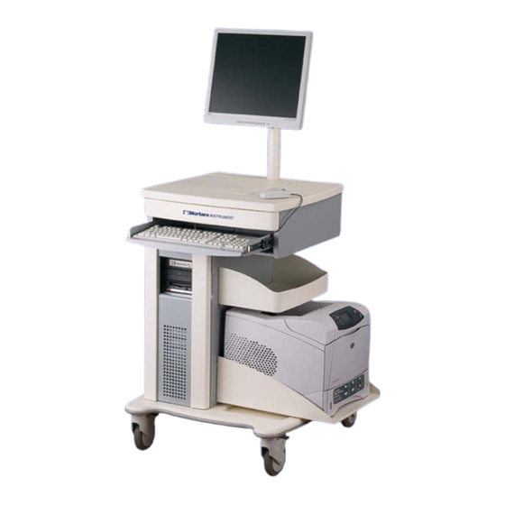
Page 20: Completed X-Scribe System
MORTARA INSTRUMENT SPECIFICATION MIS-11-151-01 Rev. 9 COMPLETED X-SCRIBE SYSTEM Finished Cart with the Laser Printer configuration and no Computer components. Finished Cart with the Thermal Writer configuration and Computer components installed. © 2007-10 Mortara Instrument, Inc. CONFIDENTIAL PAGE 20 OF 22... -
Page 21: M12C-Usb, M12Rf2500-Usb, And M12Rf608-Usb Installation
Antenna Cable (3602-004, Qty 2) Antenna (3600-002, Qty 2) Adjustable Clip (7500-010, Qty 2) TNC to BNC adapter (3601-001, Qty 2) USB type A to B Cable (6400-012, Qty 1) © 2007-10 Mortara Instrument, Inc. CONFIDENTIAL PAGE 21 OF 22... -
Page 22: Tango Nibp Mounting Bracket (Optional)
Please note that the unit may be placed at an elevation of choice before tightening the screws in Location 4. 8. Review Tango Mounting instructions in SunTech Operators Manual. © 2007-10 Mortara Instrument, Inc. CONFIDENTIAL PAGE 22 OF 22...
Need help?
Do you have a question about the X-Scribe and is the answer not in the manual?
Questions and answers