Table of Contents
Advertisement
Quick Links
Multi-Frequency Receivers
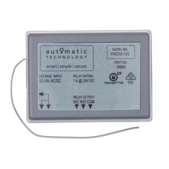
FHCRX-1V2, FHCRX-2V2 and FHRX-2V2 Installation Instructions
Thank you for purchasing an ATA Receiver. Familiarise yourself with the following instructions prior to commencing set up. Store this
information in a safe place for future reference. There are 2 types of Multi-Frequency Receivers;
a. The FHCRX-1 or FHCRX-2 series receivers have relays on board which provide normally open or normally closed contact for controlling
virtually any electronic device including garage doors and gate openers. The relays can be programmed to any three modes - pulse,
hold or timer. One or both relays can be programmed with any of the three modes.
NOTE: Timer mode is select able only with the ATA Programmer. Refer to the Programmer's manual for instructions on setting Timer
mode.
b. The FHRX-2 receiver has transistors on board which provide an open collector contact for controlling virtually any electronic garage
door or gate.
SETTING RELAY OPERATING MODES (FHCRX-1V2 and FHCRX-2V2)
Pulse Mode - Relay contact is active whilst transmitter button is pressed.
Hold Mode - Relay changes state at each press of transmitter button. Hold, Release, Hold,
etc. (like an on/off switch).
Timer Mode - Relay will remain active for the programmed duration.the timer is adjustable
from 0 seconds to 655.34 seconds in .01second steps
RELAY-1 Pulse Mode - Remove JP1 jumper or do not bridge the two pins.
RELAY-1 Hold Mode - Bridge the two pins on JP1 jumper.
RELAY-2 Pulse Mode - Remove JP2 jumper or do not bridge the two pins.
RELAY-2 Hold Mode - Bridge the two pins on JP2 jumper.
PG3-CONNECTOR
SW1
PWR SKT NC NO COM
FHCRX-1V2
ANTENNA
SHIELD
1
2
3
4
5
6
PIN1 = OPEN COLLECTOR CH1 OUT PUT.
PIN2 = 9 TO 24 VOLT DC INPUT SUPPLY.
PIN3 = NOT USED.
PIN4 = OPEN COLLECTOR CH2 OUT PUT.
PIN5 = GROUND.
PIN6 = GROUND.
FHRX-2V2
Doc # 160025_00
Part # 13365
Released 16/09/13
LED
JP1
HOW TO CONNECT FHRX-2V2 RECEIVER WITH ATA HARNESS
TO DOOR/GATE OPENERS:
PG3 CONNECTOR
SW2
D1
SW1
PG3-CONNECTOR
LED
SW1
JP1
PWR SKT NC NO COM
FHCRX-2V2
CONNECTING FHRX2V2 TO GDO-6, GDO-9, GDO-11, NEOSLIDER
BLACK
OSC
V+ or 24V+
RED
OV
BLUE
SW2
JP2
NC NO COM
ANTENNA
SHIELD
PG3 CONNECTOR
1
2
3
4
5
6
SW2
D1
SW1
Advertisement
Table of Contents

Related Manuals for Automatic Technology FHCRX-1V2


Summary of Contents for Automatic Technology FHCRX-1V2
- Page 1 The FHRX-2 receiver has transistors on board which provide an open collector contact for controlling virtually any electronic garage door or gate. SETTING RELAY OPERATING MODES (FHCRX-1V2 and FHCRX-2V2) Pulse Mode - Relay contact is active whilst transmitter button is pressed.
- Page 2 TRIOCODE 128 TECHNOLOGY Only transmitters with the TrioCode 128 Technology can operate with the latest Receivers, reducing the chance of interference from other radio frequency sources. TrioCode 128 transmitters have the ability to code into earlier model receivers. Every time a transmitter is used a new security code is generated from over 100 billion possible code combinations.
- Page 3 250 Transmitters 250 Transmitters Programmable Modes: Pulse, Hold, Timer* Controlling Outputs FHCRX-1V2 1 x Common Output 1: 1 x Normally Open Open collector output at pin one for channel 1 x Normally Closed one (40 dc volts 100 ma max)
- Page 4 Product. © August 2013 Automatic Technology (Australia) Pty Ltd. All rights reserved. TrioCode™128 is a trademarks of Automatic Technology (Australia) Pty Ltd. No part of this document may be reproduced without prior permission. In an ongoing commitment to product quality we reserve the right to change specification without notice.
Need help?
Do you have a question about the FHCRX-1V2 and is the answer not in the manual?
Questions and answers