
Related Manuals for Flintec FT-13

Summary of Contents for Flintec FT-13
- Page 1 WEIGHING CONTROLLER FT-13 For Firmware Version 2.13 and higher Flintec GmbH Bemannsbruch 9 74909 Meckesheim GERMANY www.flintec.com...
-
Page 2: Table Of Contents
Programme 7: Filling the bag ........................... 26 7.3.9 Programme 8: Bag filling from hopper scale ....................27 Target and Preset Entry........................29 Recipe Memory ............................. 30 Setup..............................31 Error Messages ............................ 33 FT-13 Technical Manual, Rev. 1.40 March 2013 Page 2 of 56... - Page 3 Appendix 4: Profibus DP / ProfiNet Data Structure ..................49 Appendix 5: CANopen Data Structure ......................51 Appendix 6: Error Table ............................ 53 Appendix 7: Parameter’s Default Table ......................54 FT-13 Technical Manual, Rev. 1.40 March 2013 Page 3 of 56...
-
Page 4: Safety Instructions
FLINTEC reserves the right to revise this manual and alter its content without notification at any time. Neither FLINTEC nor its affiliates shall be liable to the purchaser of this product or third parties for damages, losses, costs, or expenses incurred by purchaser or third parties as a result of: accident, misuse, or abuse of this product or unauthorized modifications, repairs, or alterations to this product, or failure to strictly comply with FLINTEC operating and maintenance instructions. -
Page 5: Declaration Of Conformity
2. D ECLARATION OF ONFORMITY FT-13 Technical Manual, Rev. 1.40 March 2013 Page 5 of 56... -
Page 6: Overview
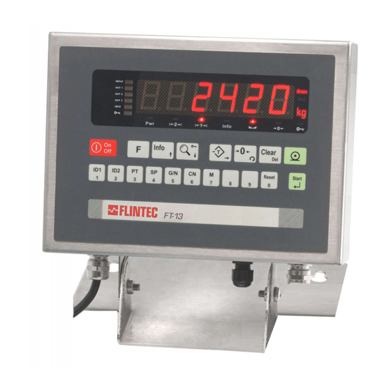
2004/22/EC directive and EN 45501 standard. It has a large 6 digit LED weight display (red, 20 mm or 14 mm high) with weight status information. With a variety of interface options FT-13 is the perfect fit to weighing systems and process control systems. -
Page 7: Technical Specifications
DC Power supply Environment and Enclosure Operation temp.: -10 °C to +40 °C legal for trade; max. 85% RH, non-condensing Enclosure Panel type (front panel IP65) or stainless steel (IP65) FT-13 Technical Manual, Rev. 1.40 March 2013 Page 7 of 56... -
Page 8: Housing Dimensions
1 6 4 1 6 4 5, mounting with 4x M4 S ticke r S ticke r Panel type rear view The hole dimensions for mounting on a panel FT-13 Technical Manual, Rev. 1.40 March 2013 Page 8 of 56... -
Page 9: Installation And Commissioning
4.2.1 Power Supply and Grounding FT-13 is available with 230 V AC power supply or 24 V DC or 12 V DC power inlet. The 230 V AC indicators are supplied with a power cable; the DC indicators are supplied with a special connector for the power inlet. -
Page 10: Standard Load Cell Connection
Connector body 4.2.3 Digital I/O Connections FT-13 is equiped with a digital I/O board which provides 4 digital inputs and 8 digital outputs. The meanings of the various I/O depend on the selected standard filling programme (see chapter 7). Pin no. (SS**) Programme Pin no. -
Page 11: Commissioning
Additional Digital I/O Board Depending on the housing type an additional digital I/O board can be added to FT-13. The additional inputs and outputs are not used in the standard filling programmes, but can be used depending on the customized application programming (requires special development order from the customer and customized firmware programming in the factory). -
Page 12: Front Panel And Keypad
Figure 5.1 Front panel view of FT-13 The weight display of FT-13 is a 6 digit LED with 14 mm or 20 mm height. At the right side of the display there are three status LEDs for indicating “Gross”, “Net” and the standard unit “kg”. -
Page 13: Keypad
The LED with the key sign (below the display) indicates the keys are locked. The key lock is automatically activated during the filling process except for the <Start> key and the <Reset> key. FT-13 Technical Manual, Rev. 1.40 March 2013 Page 13 of 56... -
Page 14: Setup And Calibration
[80-] Legal Metrological Records [800] Counter This counter increases automatically by 1 after starting the setup mode with enabled calibration jumper and service password. This counter cannot be changed manually. FT-13 Technical Manual, Rev. 1.40 March 2013 Page 14 of 56... -
Page 15: Configuration Parameters
The value will be confirmed by pressing the <Enter> key. Display resolution of the scale will be selected by the <Zero> key. [ XXXXXX ] The selection will be confirmed by pressing the <Enter> key. FT-13 Technical Manual, Rev. 1.40 March 2013 Page 15 of 56... -
Page 16: Scale Calibration
[SAvE ] message. You can confirm the “Save span adjustment under load” by pressing <Enter> or cancel it by pressing the <F> key. FT-13 Technical Manual, Rev. 1.40 March 2013 Page 16 of 56... -
Page 17: Filling With Ft-13
7. F FT-13 ILLING WITH 7.1 Overview FT-13 has 9 standard filling programmes for common filling applications as indicated below. Programme Description Typical Application Filling above the open container Liquid or bulk filling into container Filling below the bunghole of the container... -
Page 18: Filling Programmes
Filling can be done as Gross or Net Process Parameters Description When FT-13 is in the “Ready” status (the top LED in the LED bar is “on” ) press the keys shown on the left sequentially. “d_FıLL“ means a start delay. -
Page 19: Programme 1: Bunghole Container Filling
Filling can be done as Gross or Net Process Parameters Description When FT-13 is in the “Ready” status (the top LED in the LED bar is “on” ) press the keys shown on the left sequentially. “d_FıLL “ means a start delay. -
Page 20: Programme 2: Below Surface Filling
F T -1 3 scale. Process Parameters Description When FT-13 is in “Ready” status (the top LED in the LED bar is “on” ) press the keys shown on the left sequentially. “d_FıLL “ means a start delay. d_FıLL When the start input is activated, the filling starts after the start delay. -
Page 21: Programme 3: Filling And Emptying Type 1
It is emptied totally by activating the discharge input F T -1 3 F T -1 3 The process ends when the weight goes into zero range after emptying FT-13 Technical Manual, Rev. 1.40 March 2013 Page 21 of 56... - Page 22 Process Parameters Description When FT-13 is in the “Ready” status (the top LED in the LED bar is “on” ) press the keys shown on the left sequentially. This is the delay time at the end of emptying. The bottom d_dıSC...
-
Page 23: Programme 4: Filling And Discharging
3000 kg and 180kg can be discharged sequentially. Process Parameters Description When type FT-13 is in the “Ready” status (the top LED in the LED bar is “on” ) press the keys shown on the left sequentially. d_∩SG This is the period for displaying messages to be shown after filling and discharging. -
Page 24: Programme 5: Charging And Discharging
F T -1 3 F T -1 3 Process Parameters Description When type FT-13 is in the “Ready” status (the top LED in the LED bar is “on” ) press the keys shown on the left sequentially. d_∩SG The period for the [dSChrG ] message is shown after the discharging. -
Page 25: Programme 6: Filling And Emptying Type 2
[501]=00 Process Parameters Description When type FT-13 is in the “Ready” status (the top LED in the LED bar is “on” ) press the keys shown on the left sequentially. This is the delay time at the end of emptying. The bottom d_dıSC... -
Page 26: Programme 7: Filling The Bag
“clamp is closed” input is active. At the end of the filling FT-13 waits for the “d_End delay” time to release the clamp. The process cycle ends when the load is removed from the scale. -
Page 27: Programme 8: Bag Filling From Hopper Scale
This message is displayed until the detecting clamp switch hoLd after the clamp output is activated. FT-13 waits for the clamp switch input for 5 seconds. If the input is not set within 5 s the “clamp position error“ will be set. - Page 28 Process parameters Description When type FT-13 is in the “Ready” status (the top LED in the LED bar is “on” ) press the keys shown on the left sequentially. The emptying delay time is used to empty the weighing d_diSc hopper.
-
Page 29: Target And Preset Entry
Attention: Changing the target value does not require a change of the coarse lead-in and fine lead-in values in general. Warning: For accurate filling the coarse lead-in and fine lead-in values must be choosen carefully. FT-13 Technical Manual, Rev. 1.40 March 2013 Page 29 of 56... -
Page 30: Recipe Memory
Press the <8> key. To reach the recipe you want, use the arrow < > and < > rEC. XX keys. Press <Enter> to choose the recipe for the next filling process. FT-13 Technical Manual, Rev. 1.40 March 2013 Page 30 of 56... -
Page 31: Setup
X] Preact correction frequency Type FT-13 can adjust the fine value according to the filling error of the previous filling cycle. The preact adjustment is applied each time after a certain number of filling cycles which is defined here to decrease the filling time. - Page 32 The fine feed starts by the <Start> key hold pressed for one second. After test feeding the display shows the quantity of material fine lead in as [ XXXXXX ]. FT-13 Technical Manual, Rev. 1.40 March 2013 Page 32 of 56...
-
Page 33: Error Messages
The total weight value is higher than [t_trGT]. t ovEr Clear the total weigt for starting the process again. Valid for programme 6. Clamp position error. E CLMP Valid for programme 7. FT-13 Technical Manual, Rev. 1.40 March 2013 Page 33 of 56... -
Page 34: Communication
Termination (RS 485) Not used Termination (RS 485) Not used A; Par. [02-] B; Par. [02-] T-; Par. [02-] Not used +24V; 20 mA CL Not used Shield D25 body FT-13 Technical Manual, Rev. 1.40 March 2013 Page 34 of 56... -
Page 35: Continuous Output Mode
8.2.4 Host Mode The indicator can communicate with a PC in host mode. You can upload or download data to the indicator by adjusting the related interface parameters within the FLINTEC IndFace software. 8.2.5 Print Mode The print mode is not available for more than one interface. -
Page 36: Setup
0 : 1 200 Baud 4 : 19 200 Baud 5 : 38 400 Baud 6 : 57 600 Baud [022 X] Handshake 0 : No Handshake 1 : Xon/Xoff FT-13 Technical Manual, Rev. 1.40 March 2013 Page 36 of 56... -
Page 37: Ethernet Option
Full Duplex Connection to an Ethernet hub Cabling is done using a standard RJ-45 patch cable. Direct connection to a PC Cabling is done using a RJ-45 cross over cable. FT-13 Technical Manual, Rev. 1.40 March 2013 Page 37 of 56... -
Page 38: Setup
For older instruments the configuration will be done by the Ethernet Device Installer PC software, see separate document on the Flintec Product-CD. Step 1: Install the Ether X software from the Flintec Product-CD to any PC on the network Step 2: Start the Ether X software After pressing the “Search”... -
Page 39: Data Structure
See Chapter 8.2.5 and 8.2.6 parameter [040] Host mode Modbus RTU See Appendix 3 [031 XX] Address The address of the instrument will be entered via numerical keypad in the range 01 to 99. FT-13 Technical Manual, Rev. 1.40 March 2013 Page 39 of 56... -
Page 40: Profibus Option
Appendix 4. Important hint: During the setup the Profibus output (weight value and status bits) will not be updated. 8.5.3 Data Structure See Appendix 4. FT-13 Technical Manual, Rev. 1.40 March 2013 Page 40 of 56... -
Page 41: Profinet Option
The ProfiNet communication will be configured by the EtherX PC software. EtherX can be installed from the Flintec Product CD-ROM. The EDS file is available on a CD which is supplied together with the instrument. After the setup of these parameters and the hardware connection as described above, the data interface can be used as described in Appendix 4. -
Page 42: Canopen Option
Appendix 5. Important hint: During the setup the CANopen output (weight value and status bits) will not be updated. 8.7.3 Data Structure See Appendix 5. FT-13 Technical Manual, Rev. 1.40 March 2013 Page 42 of 56... -
Page 43: Diagnostics
When pressing the <Enter> key the [ Ld dEf ] message appears on the display. Press the <Tare> key for loading the default values or press the <F> key to go to “9-“ sub block. FT-13 Technical Manual, Rev. 1.40 March 2013 Page 43 of 56... -
Page 44: Appendix 1: Setup And Calibration Menu
Editable with any Editable with service Editable with service Editable with service password and calibration password and calibration password and calibration password password password password password password jumper jumper jumper FT-13 Technical Manual, Rev. 1.40 March 2013 Page 44 of 56... -
Page 45: Appendix 2: Continues Output Mode Data Structure
Always = 0 Bit 6 Always 0 Bit 7 Bit 7 STX = 0x02 CR = 0x0D CSUM = 0 – (STX + STATUS A + … + CR) FT-13 Technical Manual, Rev. 1.40 March 2013 Page 45 of 56... -
Page 46: Appendix 3: Modbus Rtu Data Structure
(40031-32) – Check load cell connections Scale unstable – Wait until scale becomes stable – Check grounding wiring Calibration Jumper is not installed- Check Calibration jumper FT-13 Technical Manual, Rev. 1.40 March 2013 Page 46 of 56... - Page 47 40 054 00,34 00,02 GR-NET 40 056 40 058 40 060 40 062 40 064 40 066 40 068 40 070 40 072 40 074 40 076 40 078 FT-13 Technical Manual, Rev. 1.40 March 2013 Page 47 of 56...
- Page 48 8. When the CRC is placed into the message, its upper and lower bytes must be swapped as described below. Attention: For hardware connection details please refer to the related hardware descriptions within this manual For more Modbus information please refer to the web site http://www.modbus.org FT-13 Technical Manual, Rev. 1.40 March 2013 Page 48 of 56...
-
Page 49: Appendix 4: Profibus Dp / Profinet Data Structure
DP / P PPENDIX ROFIBUS ROFI TRUCTURE The output from FT-13 on PLC requests is in four words and according to the table below. FT-13 Output Bit no. Word W30 W29 W28 W27 W26 W25 W24 W23 W22 W21 W20... - Page 50 Any input to FT-13 is in four words and according to the table below. FT-13 Input Bit no. Word Word Word Pause Hold Dschrg Reset Start Clear Tare Zero Command Word Not in use Expanded Commands Here the first and the second word describe the value received from the PLC, the third and the fourth word the meaning as indicated below.
-
Page 51: Appendix 5: Canopen Data Structure
5: CAN PPENDIX OPEN TRUCTURE The output from FT-13 on PLC requests is in two double words and according to the table below. FT-13 Output Bit no. W30 W29 W28 W27 W26 W25 W24 W23 W22 W21 W20 W18 W17... - Page 52 0000 0100 Span calibration in process 0000 1001 Calibration error (see bit 15...8) Any input to FT-13 is in two double words and according to the table below. FT-13 Input Bit no. W30 W29 W28 W27 W26 W25 W24 W23 W22 W21 W20 W19...
-
Page 53: Appendix 6: Error Table
RROR ABLE The FT-13 Weighing Controller has been designed as very reliable and virtually error free instruments. However if an error occurs do not attempt to repair the equipment before you understand what caused the error. Note the problems you have with your instrument and the error messages shown on the display. Then try to solve the problem according to the error table given below. -
Page 54: Appendix 7: Parameter's Default Table
6 kg / 0.001 kg 990 All parameters Calibration / Adjustment 991 Load default parameters 30- Calibration 301 Calibration 31- Adjustment 310 Zero adjustment 311 Span adjustment 312 Span adjustment under load FT-13 Technical Manual, Rev. 1.40 March 2013 Page 54 of 56... - Page 55 FT-13 Technical Manual, Rev. 1.40 March 2013 Page 55 of 56...
- Page 56 FT-13 Technical Manual, Rev. 1.40 March 2013 Page 56 of 56...
Need help?
Do you have a question about the FT-13 and is the answer not in the manual?
Questions and answers
Error 3900