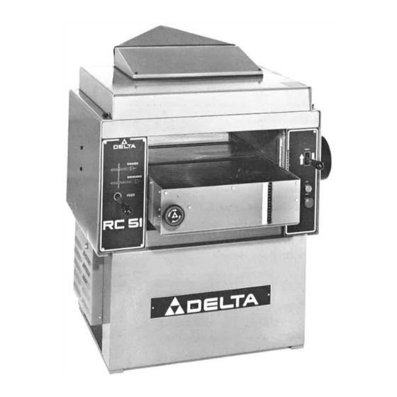
Summary of Contents for Delta RC-51
- Page 1 20" Planer (Model RC·S1) » » DATED 1-20-92 PART NO. 1345297 Delta Internallonal Machinery Corp 1992 CE LT A ••...
-
Page 2: Table Of Contents
TABLE OF CONTENTS SAFETY RULES ADDITIONAL SAFETY RULES FOR P LANERS UNPACKING AND CLEANING THE MACHINE .. 4 ASSEMBLING DUST CHUTE ELECTRICAL CONNECTIONS OPERATING CONTROLS On/Off Controls ............6 R aising And Lowering The Table Feed Roll Speeds Table Rollers... -
Page 3: Safety Rules
If you have any questions relative to its application DO NOT use the machine until you have written Delta Machinery and we have advised you. DELTA INTERNATIONAL MACHINERY CORP. -
Page 4: Additional Safety Rules For Planers
ADDITIONAL SAFETY RULES FOR PLANERS MAKE SURE the blades are properly secured in the IF YOU ARE NOT thoroughly familiar with the opera cutterhead, as explained in the instruction manual, before tion of planers, obtain advice from your supervisor, instructor or other qualified person. turning on power. -
Page 5: Assembling Dust Chute
ASSE MBLING D UST CHUTE To assemble the dust chute to your planer, remove the Fig. 5 three screws (A) Fig. 5, from the rear of the planer. The dust chute is then assembled to the rear of the planer, as shown in Fig. -
Page 6: Operating Controls
OPERATING CONTROLS ON/OFF CONTROLS The machine is started by pressing the green (shrouded) "ON" button (A) Fig. 10. To stop the machine, push red (mushroom type) "OFF" button (8). RAISING AND LOWERING THE TABLE For fast and easy changes in thickness settings to accom modate thick or thin stock, the table can be rapidly raised Fig. -
Page 7: Feed Roll Speeds
FEED ROLL SPEEDS Your planer is supplied with feed roll speeds of feet per minute if it is a single phase machine and feet per minute if it is a three phase machine. When feed roll engagement lever (A) Fig. is all the way in Fig. -
Page 8: Anti-Kickback Fingers
TABLE ROLLERS Your planer is supplied with two table rollers (A) Fig. 16, which aid in feeding the stock by reducing friction and turn as the stock is fed through the planer. It is not possible to give exact dimensions on the proper height setting of the table rollers because each type of wood behaves differently. -
Page 9: Checking And Adjusting Drive Belt Tension
CHECKING AND ADJUSTING DRIVE BELT TENSION Proper drive belt tension is obtained when there is 1/4" deflection, using light finger pressure on drive belts (A) Fig. midway between pulleys. If an adjustment is necessary proceed as follows: MAKE CERTAIN THE MACHINE IS DISCON Fig. -
Page 10: Checking, Adjusting And Repl Acing Knives
CHECKING , ADJUSTING AND REPLACING KNIVES When checking, adjusting or replacing the cutterhead knives on the 20" Planer, proceed as follows: DISCONNECT THE MACHINE FROM THE POWER SOURCE AND REMOV. E THE TOP COVER OF THE PLANER EXPOSING THE CUTTERHEAD. A. -
Page 11: Adjusting Spring Tension On Feed Rollers
ADJUSTING SPRING TENSION ON FEED ROLLERS The outfeed roll (A) Fig. 22, and infeed roll (not visible) are those parts of your planer that feed the stock while it is being planed. The feed rolls are under spring tension and this tension must be sufficient to feed the stock uniformly through the planer without slipping but should not be too tight that it causes damage to the board. -
Page 12: Adjusting Pressure Bar
ADJUSTING PRESSURE BAR The pressure bar is located directly behind the cutter head and rides on the planed surface of the stock press ing the stock down on the table. The pressure bar must be parallel to the knives and tangent to the table and set below the cutting circle. -
Page 13: Adjusting Chip Deflector
Place the gage block (A) Fig. underneath outfeed roll (C). The bottom of outfeed roller (C) should just touch .035" the top of gage block (A) which would be below the cutting circle. Fig. If an adjustment is necessary, loosen locknut (0) Fig. -
Page 14: Adjusting Table Height Scale
ADJUSTING TABLE HEIGHT SCALE Fig. 33 The table height scale is adjusted at the factory and indicates the distance from the table to the cutting circle (depth of cut). To check and adjust the pointer, proceed as follows: Run a piece of wood part way through the planer and stop the machine. - Page 15 With a feeler gage (D) Fig. measure the gap be tween the table surface and the straight edge (8) near the infeed roll (E). If an adjustment to the infeed roller (E) Fig. necessary, loosen set screw (F) Fig. located under Fig.
-
Page 16: Leveling The Table
LEVELING THE TABLE The table is set parallel to the cuttinghead at the factory and no further adjustment should be necessary. If your machine is planing a taper, first check to see if the knives are set properly in the cutterhead. Then check to see if Fig. -
Page 18: Authorized Service Stations
De lta M ach i ne ry Delta will repair or replac� . at its expense and at its option, any Delta machine, machine part, or machine accessory which in normal use has proven to be defective in workmanship or material, provided that...


Need help?
Do you have a question about the RC-51 and is the answer not in the manual?
Questions and answers