
Related Manuals for JBI PUNCH-BIND


Summary of Contents for JBI PUNCH-BIND
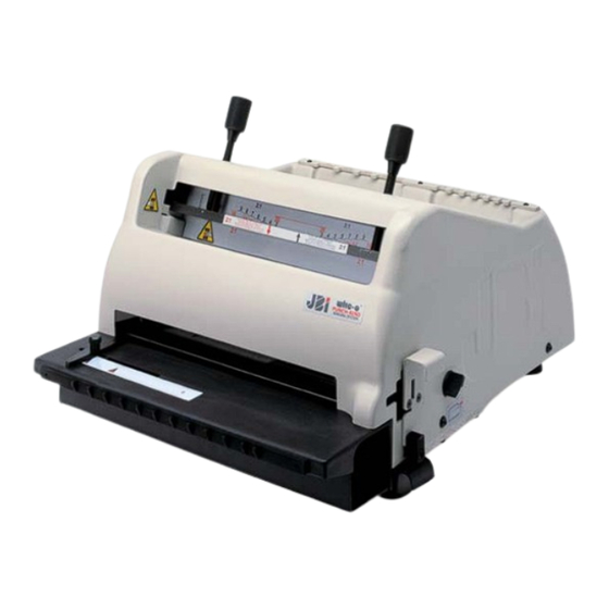
- Page 1 PUNCH-BIND ELECTRIC PUNCHING AND BINDING MACHINE ( from serial number PB.001) OPERATING MANUAL Version 230V ISSUE 1 January 2003 --------------------------------- SERIAL NO. --------------------------- SHIPPING DATE...
- Page 2 INTRODUCTION lso in the ongoing effort to improve the hank you for buying the Punch-Bind quality performance this punching/binding machine, JAMES BURN electric punching/binding machine from James Burn International. This handbook INTERNATIONAL reserve the right to is designed to help you in getting the most make changes.
- Page 3 INTRODUCTION If you have any questions about your Punching Machine or this manual, please contact your local James Burn International agent or office shown below : Your local James Burn International agent or office...
-
Page 4: Table Of Contents
CONTENTS USING YOUR PUNCHING/BINDING MACHINE SAFELY Safety warnings for your punching/binding machine Warning signs on your punching/binding machine INSTALLING YOUR PUNCHING/BINDING MACHINE Lifting the machine GENERAL DESCRIPTION DRIVE INFORMATION FOR PUNCHING SECTION OF YOUR MACHINE INSTALLING/CHANGING A PUNCH TOOL STARTING UP PROCEDURE SETTING UP FOR PUNCHING PUNCHING PROCEDURE UNJAMMING PROCEDURE FOR THE PUNCHING SECTION... - Page 5 CONTENTS TECHNICAL SPECIFICATIONS 21.1 Machine specifications 21.2 Electrical specifications WARRANTY POLICY WARRANTY CARD DECLARATION OF CONFORMITY...
-
Page 6: Using Your Punching/Binding Machine Safely
1. USING YOUR ELECTRIC PUNCHING/BINDING MACHINE SAFELY Learn to recognise safety information and always follow recommended precautions and safe operating practices. Here is the Safety-Alert symbol : When you see this symbol on your punching / binding machine, or in this handbook, be alert to the potential for personal injury or property damage. - Page 8 SAFETY WARNINGS FOR YOUR PUNCHING / BINDING MACHINE his section lists the safety warnings that you should be familiar with before you try to install or operate your punching/binding machine. DANGER lectrical Shock Hazard PROTECT CHILDREN eep children away from your punching / binding machine. Never allow children to operate your punching / binding machine IF YOU NEED THIS HANDBOOK IN ANOTHER LANGUAGE...
-
Page 9: Safety Warnings For Your Punching/Binding Machine
SAFETY WARNINGS FOR YOUR PUNCHING / BINDING MACHINE KEEP SAFETY LABELS CLEAN AND IN GOOD CONDITION o not remove any safety labels from your punching / binding machine. Keep all safety labels clean and in good condition. Replace all safety labels missing or damaged. KEEP HANDS CLEAR OF THE CLOSING BAR ®... - Page 10 SAFETY WARNINGS FOR YOUR PUNCHING / BINDING MACHINE NOTE TO EMPLOYERS o you know your responsibilities as an employer. Make sure that all employees know how to operate safely the machine and have read this handbook. Make sure your employees are aware of the safety warnings on the punching / binding machine and in this handbook.
-
Page 11: Warning Signs On Your Punching/Binding Machine
WARNING SIGNS ON YOUR PUNCHING / BINDING MACHINE Keep your hands away from the closing bar WARNING --------- DISCONNECT THE MAINS SUPPLY BEFORE REMOVING THIS COVER AND WAIT 15 MINUTES BEFORE ANY OPERATION Conformity plate at the rear of the machine... -
Page 12: Installing Your Punching/Binding Machine
INSTALLING YOUR ELECTRIC PUNCHING / BINDING MACHINE d is an office machine. It must be positioned in such a way as to allow access to the perforation tray from the right side of the machine. It will also need clearance behind the machine for adequate ventilation. -
Page 13: General Description
GENERAL DESCRIPTION lectrically operated punching. Punches up to 2 mm or 25 sheets of 80gsm paper, in using the full width, that is to say 330mm. ® Binds Wire-O from N° 3 to N° 20 (3/16" to 1" 1/4) The machine may be plugged into any earthed single phased socket 16A (protection C 30mA). CAUTION : We disclaim liability if you punch only acetate sheets. -
Page 14: Drive Information For Punching Section Of Your Machine
DRIVE INFORMATION FOR PUNCHING SECTION OF YOUR MACHINE 12 he machine is driven by a three-phase motor (P : 0.25 Kw), controlled by an inverter with vectorial flow control which controls the up and down movement of the punch tool. The up and down movement is carried out by an eccentric, which via a connecting rod and yoke enables the punch pins to move up and down. -
Page 15: Installing/Changing A Punch Tool
INSTALLING / CHANGING A PUNCH TOOL Set the rocker switch in the backward position. Press the foot pedal twice to allow the tool to go to its low position Release the tool by turning the fixing pin anticlockwise. Pull the tool by its handle slowly to remove it from the machine, placing your hand underneath to support it. - Page 16 INSTALLING / CHANGING A PUNCH TOOL NB : before engaging the new tool, make sure that pins overlapping the sheet edges are in a retractable position (retractable pins pulled towards the operator, see picture page 13). 5.5.1. : for punching 11" sheet with 3/1" pitch, you need to retract one pin at each side of the sheet to be perforated (pin n°7 and 34 marked in red).
-
Page 17: Starting Up Procedure
STARTING UP PROCEDURE Connect the plug of your machine to mains power supply. At the back of the machine, press on the circuit breaker « 1-0 » the LED (see picture page 16) located on the right side of the closing bar will light up. The circuit breaker is then in position «... -
Page 18: Setting Up For Punching
SETTING UP FOR PUNCHING Start up the machine as in Section 6. STARTING UP PROCEDURE Place a sample sheet of paper fully into the punching slot so that it contacts the back of the slot squarely. -IMPORTANT : Always centre the punching area in the middle of the tool to avoid having an irregular pressure and a premature wear both of the tool and the machine. -
Page 19: Punching Procedure
PUNCHING PROCEDURE T he number of SHEETS that can be punched in one bite will vary according to the type of paper being used. This will normally be a maximum of 25 sheets of 80gsm paper according to tool version (about 2 to 2.5 mm). The method of punching is as follows : See NOTE for acetate paper Place a pile of work face downwards neatly at one side of the unit, with the binding edge away from you. - Page 20 PUNCHING NOTE 1 Ensure that the printed text is returned to its original collated order after punching. The covers are added to the contents at the WIRE-O® inserting stage. NOTE 2 When covers are larger than the contents these should be punched separately and the lay gauge adjusted accordingly.
-
Page 21: Unjamming Procedure For The Punching Section
UNJAMMING PROCEDURE FOR THE PUNCHING If the machine jams, set the rocker switch in the backward position and press the foot pedal once to allow the tool to come back to its high position. NOTE : this operation allows disengaging pins from the sheets and then to remove these sheets. -
Page 22: Selection Of Wire-Osize
® 1 0. SELECTION OF WIRE-O SIZE T he selection of a correct size of WIRE-O® binding is important, in order to obtain a neat presentation and a professionally finished book. A measuring gauge (capacity selector) is provided at the rear of the paper tray to determine the correct size number. 10.1 Holding the complete book together with covers, determine which slot matches the thickness of the book by sliding the book into the correct upright gap of the capacity selector. -
Page 23: Inserting The Wire-Obinding Element
® 1 1. INSERTING THE WIRE-O BINDING ELEMENT P rior to inserting WIRE-O® element, arrange the book so that it is face down in the following order, back cover at the bottom followed by the front cover and then the contents. To insert WIRE-O®... - Page 24 BINDING INFORMATION NOTICE ® Prior to closing the Wire-O element into the book, complete the following procedure : 15.1 ADJUSTMENT OF THE CLOSING TOOL The adjustment is carried out by using the 2 adjustment screws to move down and up the closing bar. Both adjustment screws must be actioned in parallel. Do not use any tool to loosen the 2 screws.
-
Page 25: Closing Tool Adjustment
CLOSING TOOL ADJUSTMENT 12.1 SAFETY WARNINGS DURING THE CLOSING TOOL 4 never push objects in the closing jaws. It may cause damage. 4 never forget to switch the machine OFF and remove power cable before taking care of the closing jaws. 4 2 sensors placed underneath the closing bar lock the machine and cut the power supply of the motor if they are occulted. -
Page 26: Closing Of Wire-O ® On Your Machine
® 1 3. CLOSING OF WIRE-O . ON YOUR MACHINE 13.1 With one hand, place a book with its inserted WIRE-O® into the binding section of the unit (between the fixed side and adjustable closing bar so that the open ends of the WIRE-O® element are resting squarely on the platform). -
Page 27: Repositioning Of
1 4. REPOSITIONING OF BACK COVER 17.1 Hold the book. 17.2 Turn the back cover around the WIRE-O® binding. 17.3 Lay the book flat to complete the operation. -
Page 28: How To Empty The Perforation Tray
1 5. HOW TO EMPTY THE PERFORATION TRAY NOTICE The perforation tray slides out from underneath the table. It holds confettis (paper punching) which are created when punching and must be emptied regularly. 18.1 Pull out the confetti tray by the handle (by the right side). 18.2 Empty the confetti tray. -
Page 29: Maintaining Your Punching/Binding Machine
1 6. MAINTAINING YOUR ELECTRIC PUNCHING/BINDING MACHINE NOTICE his is an important section and any lubrication recommended in Section 16.1 on GENERAL MAINTENANCE can be applied by any user of this machine providing they follow the procedure and only use the recommended lubricants. Use of the wrong lubricants may damage your punch tool. -
Page 30: Fault Finding Procedure
FAULT FINDING PROCEDURE WARNING For replacement of circuit board, please contact the after-sales department SYMPTOM POSSIBLE CAUSES ACTION Machine will not operate when a) No power a) Check mains plug well switched on (the sensor on right connected b) Power fuse blown or no fuse side if off) b) Check the 2 fuses on circuit c) Inverter blocked jam... -
Page 31: Information : Protection Guard / Table
INFORMATION : PROTECTION GUARD / TABLE NOTICE Do not remove from the machine : The table The tool guard The machine housing These parts are set by the manufacturer. If, for any reason it becomes necessary to remove any of the above items, then contact the after sales department. Machine housing Table... -
Page 32: Selling, Transferring Or Disposing Of Your Punching/Binding Machine
SELLING / TRANSFERRING OR DISPOSING OF YOUR PUNCHING / INDING MACHINE 19.1 SELLING OR TRANSFERRING YOUR MACHINE NOTICE f you sell or transfer your machine, you must ensure the machine is in working order, the labels and this handbook are included and are in readable condition. Failure to do so could result in your being made responsible if the person to whom you sell or transfer your machine gets hurt using it. -
Page 33: Technical Specifications
2 0. TECHNICAL SPECIFICATION 20.1 MACHINE SPECIFICATION WIDTH 410 mm HEIGHT 340 mm DEPTH 800 mm NET WEIGHT 35 Kg GROSS WEIGHT 49 Kg including packaging 21.2 ELECTRICAL SPECIFICATION CAUTION his is not a dual voltage machine. Operate machine only to the supply voltage shown on the machine nameplate located at the rear. -
Page 34: 21. Warranty Policy
Consumable parts are excluded from the warranty. JBI reserves the right to request the return of any faulty part or component before a replacement is sent out on a free of charge basis. Where this is impractical or the component has not yet been returned, JBI will charge for the component upon despatch and credit the customer upon receipt of the returned faulty part. -
Page 35: 22. Warranty Card
Phone : 02 33 84 21 50 Fax : 02 33 84 21 51 ---------------------------------------------------------------------------------------------------------------------------------------------------- Réf. : Punch-Bind issue 1 REGISTRATION CARD PLEASE FILL IN AND RETURN THIS CARD TO THE RELEVANT JBI ADDRESS (see back cover of this handbook) Company name : ------------------------------------------------------------------------------------------------- Address... -
Page 36: 23. Declaration Of Conformity
: 61304 L’AIGLE CEDEX COUNTRY : FRANCE NAME, TYPE OR MODEL, BATCH OR SERIAL NUMBER ELECTRIC PUNCHING / BINDING MACHINE, MODEL PUNCH-BIND ER ISSUE 1, January 2003 Serial number PB.001 onwards SERIAL NUMBER : In application of machines directives : 98/37/CEE In application of directive CEM n°...
Need help?
Do you have a question about the PUNCH-BIND and is the answer not in the manual?
Questions and answers