Table of Contents
Advertisement
Operating
Instructions
(Modèle WOB3500 MK2)
Version : 200-240Vac 50/60Hz Single phase
Issue : 2
Serial number WOB2.211 onwards
(starting January 2009)
To: Installation Agent
After installing this machine, always
leave this manual on the machine
.
JBI James Burn Int.
®
®
Wire-O
, Lhermite
and
67 Rue du Docteur Blaizot
®
UniCoil
are registered
BP 134
Trademarks of
61304 L'Aigle Cedex
France
James Burn International
Tel: +33 (0)2 33 842150
Patent Pending
Fax: +33 (0)2 33 842151
© JBI 2000
ALPHA/OM/1
Advertisement
Table of Contents

Related Manuals for JBI Wire-O WOB3500 MK2


Summary of Contents for JBI Wire-O WOB3500 MK2
- Page 1 Version : 200-240Vac 50/60Hz Single phase Issue : 2 Serial number WOB2.211 onwards (starting January 2009) To: Installation Agent After installing this machine, always leave this manual on the machine JBI James Burn Int. ® ® Wire-O , Lhermite 67 Rue du Docteur Blaizot ®...
-
Page 2: Table Of Contents
Contents Section Page Section Title - Topic Contents Welcome Introduction Contact addresses and telephone numbers Safety information 1.Using your binding machine safely Safety warning signs on you binding machine Safety Instructions Handle heavy equipment properly Wear safe clothing Protect children Keep safety labels clean and in good condition Be prepared for emergencies... - Page 3 Section Section Page Title - Topic Hanger feed option 5. Hanger feed using Loading an hanger spool 6. Henger spool installation General maintenance 7.Maintaining your binding machine Daily maintenance Weekly maintenance Annual maintenance Ongoing maintenance 8. Spare parts Spare parts 9.Selling, transferring or disposing Selling or transferring your binding machine...
- Page 4 Introduction Thank you for purchasing a WOB3500 Binding Machine from James Burn International. This instruction manual has been prepared to help you get the most from your new binding machine. NOTICE Read this manual carefully before installing your binding machine. It is essential that you read all the instructions to ensure a safe and correct manner for operating the machine.
-
Page 5: Safety Information
Using your Binding Machine Safely Safety Information Learn to recognise safety information, and always follow recommended precautions and safe operating practices. This is the safety alert symbol: When you see this symbol on your binding machine, or in this manual, be alert to the potential for injury or property damage. - Page 6 Using your Binding Machine Safely Safety Warning Signs on your Binding Machine This section lists the safety warnings that you should be familiar with before you install or operate your binding machine. DANGER Electrical shock hazard DO NOT TOUCH THE CLOSING TOOLS IN YOUR BINDING MACHINE.
-
Page 7: Safety Instructions
Using your Binding Machine Safely SHEAR HAZARD Keep hands clear of Cutter. Turn power OFF before servicing. Safety Instructions DO NOT OPERATE THE BINDING MACHINE IF THE GUARDS ARE NOT IN PLACE All guards MUST be in place before you start the binding machine. DO NOT ADJUST THE GUARD OPENINGS WHILE THE MACHINE IS SWITCHED ON Servicing must not be carried out with the machine switched ON. -
Page 8: Handle Heavy Equipment Properly
Using your Binding Machine Safely HANDLE HEAVY EQUIPMENT PROPERLY Always handle heavy equipment with a suitable mechanical lifting device. Always position the weight of the machine on your lifting device so that it is stable when lifted. Know the weight of the equipment before attempting to lift it. -
Page 9: Keep Safety Labels Clean And In Good
Using your Binding Machine Safely KEEP SAFETY LABELS CLEAN AND IN GOOD CONDITION Do not remove any safety labels from your binding machine. Keep all labels clean and legible. Replace any missing or damaged labels. BE PREPARED FOR EMERGENCIES Be prepared for fires, injuries or other emergencies. Keep a first aid kit and a fire extinguisher handy. -
Page 10: Keep This Manual With The Binding
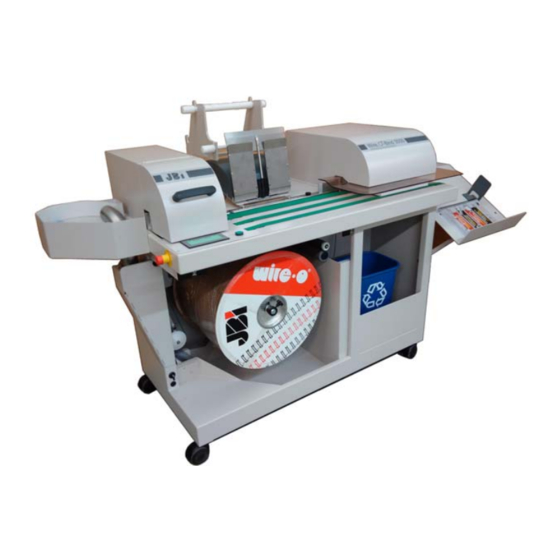
Using your Binding Machine Safely KEEP THIS MANUAL WITH THE BINDING MACHINE This manual is an important part of your binding machine. Always keep this manual where it belongs - with the binding machine IF YOU NEED THIS MANUAL IN ANY OTHER LANGUAGE If you need this manual in a language other than English, contact James Burn International. - Page 11 Using your Binding Machine Safely Warning Signs on your Binding Machine Identification Plate Adjusting square paper format Reception 2 Adjustable feet to keep the machine steady WOB3500/MesDocuments/Corinne/Notices/WOB3500/Anglais...
-
Page 12: Installation Of Your Binding Machine
Installation of your Binding Machine Installation of your Binding Machine Installation of your binding machine will depend on how you plan to use it and the resources available in your bindery. Therefore, the installation information should be considered as a guideline and recommendation rather than exact instructions. -
Page 13: Unpacking Your Binding Machine
Installation of your Binding Machine Unpacking your Binding Machine The binding machine is packed in a wooden case. To unpack: Unbolt the top and sides of the case and remove them. Check to see if any damage has occurred to the machine during transportation. Notify James Burn International and the carrier immediately regarding any damaged parts. -
Page 14: Technical Data
Installation of your Binding Machine Technical Data Standards And Application Conditions Conformity Machine directive EMC directive Approvals Acceleration Resistance up to 2g (Germanischer Lyoyd, general Vibration Resistance conditions). Climatic Conditions Class 3K3 to EN50178 (Without Condensation, Average Relative Humidity 85%) Packaging Dust Packaging t = -10ºC….+40ºC... -
Page 15: Wire Sizes
How to Select the Correct Size of Wire-O® ® ® ® Wire-O® is supplied in eleven different sizes for the WOB3500 binding machine. These range from 1/4” and 1 ” sizes and are available in a variety of finishes and colours. Request a brochure from James Burn International or your agent for the complete range. -
Page 16: Table Of Recommended Maximum Book
How to Select the Correct Size of Wire-O® ® ® ® Table of Recommended Maximum Book Thickness for each Wire Size Recommended Maximum Pitch of Wire Size Book Thickness Wire Wire No. (Inches) ¼ 3/16 5/16 ¼ 5/16 11.1 7/16 12.7 ½... -
Page 17: Initialization
Running Your Binding machine. ® It is highly recommended that only original James Burn International Wire-O spools are use with your WOB3500 binding machine. Switch on the WOB3500. On the opening screen using the ‘change switch’ select ‘spool’. NOTA : Pressing the ‘change switch’ alternates between ‘Spool’ and ‘Cut Lengths’. ‘Cut Lengths’... - Page 18 Running Your Binding machine. Cancel the initialization The screen displays Return to the previous screen The screen displays To go to next screen In case of spool without hanger option In case of spool with hanger option In case of cut lengths without hanger option In case of cut lengths with hanger option...
- Page 19 Running Your Binding machine. ® To Load a Spool of Wire-O Open the Wire caddy door. Ensure that no wire remains under the wire lift drive Spool cart. Wire caddy door. Nicking paper removal rollers. Wire lift drive. Carefully remove the spool from the shipping carton and remove the protective film. Ensure that the wire spool is aligned as shown in the photo below.
- Page 20 Running Your Binding machine. Position the spool in front of the machine with the Wire-O rolled-up clockwise, carefully lift the spool onto the spool support shaft. Grove in spool shaft. Cup hole. Turn the spool by hand until you feel drive cam pin engages in the spool. Important : push the spool end cap in further so that the cup hole engages into the groove of the spool shaft.
- Page 21 Running Your Binding machine. Support the wire with your Support the left hand. With your right wire. thumb press the cart return clip. Push the assembly back into the WOB3500. Cart return clip. Pushing the cart fully home. Important. Allow the wire to sit in the tray under the spool as shown on the picture.
- Page 22 Running Your Binding machine. Spring loaded Wire feed switch. drive. Take the end of the wire element and feed it up to the bottom wheel of the wire feed drive. Operate the spring loaded switch upwards. The wire feed motor will start to feed the wire up to the wire reservoir on the top of the machine.
-
Page 23: Reception Adjustment
Running Your Binding machine. The screen displays of of the screens indicated on page 16 according to selection done. Indicate the number of loops To release or tighten the wire. Each time – or + is (for spools only) pressed it will open or close the jaws of 0.2mm Book counter 0 to 99999 To reset the book counter End of work... - Page 24 Skip bind option : hanger unit Machine switched off, plug the hanger feed unit Fix the hanger feed unit with the 2 fixing holes On screen (previous page), select the hanger feed option (if you require this option) Come back to the screen “selection” pressing the key Select the number of loops of each cut length Select the number of cut lengths Select the length of the jump required (in number of loops)
- Page 25 Skip bind option : Hanger spool feeding Hangers stock Insert the axis (1) inside the hanger spool Put the assembly on the spool holder (upper position) Position the second axis (2) on the lower support Remove the sticks retaining the hangers Unwind slightly the hanger spool up to the beginning of the hangers stock Place the 2 lower stick rules inside the hangers stock, up to the little roller Place the 2 stick rules on the little roller, bring them up to the lower axis of the spool holder (2)
-
Page 26: General Maintenance
Maintaining your Binding Machine General Maintenance Although only limited maintenance is required, that which is required is important to enable continually safe and good machine performance. CAUTION All maintenance work should be carried out by qualified personnel maintenance engineers, service engineers, or electricians only Before commencing any maintenance work, switch OFF the machine and disconnect the electrical supply from the mains supply. -
Page 27: Spare Parts
Spare parts Recommended spare parts : 1 Off JE24004 : encoder GHT4065A3R1360 24 Vcc 1 Off JE22041 : detector OMRON E3T-SL33 24 Vcc 1 Off JE22052 : inductive detector M30 SICK 1 Off JE29065 : Sanyo card 1 Off JE07067 : contactor 12A : LC1-D12BL 24 Vcc 2 Off JE06076 : microswitch Crouzet 1 Off... -
Page 28: Selling Or Transferring Your Binding
Selling, Transferring or Disposing of your Binding Machine Selling or Transferring your Binding Machine If you sell or transfer your binding machine you must ensure that the machine is in working order, and that the labels and this manual are in a legible condition. Failure to do so could result in you being responsible to whom you sell or transfer your binding machine should it cause personal injury or damage to property Disposing of your Binding Machine... -
Page 29: Fault Finding Chart
Fault finding chart Fault Cause Remedy Display not illuminating No power supply Check power supply when machine switched ON Fuse blown Check Power Inlet Connector circuit breaker Check internal fuse to 24V : Operator panel display No power supply to PLC Check PLC connector working but no menu available... - Page 30 Fault finding chart The machine is not cycling Closing Head jammed Turn OFF power Wait 30 seconds Switch ON power Initialise the machine NOTA : the closing head is on top position and the wire is ejected at the reception 10.2 Error messages Cover open Emergency stop : off...
-
Page 31: General Data
Technical data about your Binding Machine NOTICE Your binding machine is constructed to a very high specification. Details are shown in this section. Strictly adhere to these specifications at all times! General Data Machine size Max length 2.14m Max height 1.175m Max depth 0.73m... -
Page 32: Electrical Data
Technical data about your Binding Machine Wire Size Max. Book Thickness (mm) Min. Book Thickness (mm) No.4 No.5 No.6 No.7 No.8 No.9 12.5 No.10 No.12 No.14 No.16 No.18 25.3 No.20 Electrical Data Mains electric supply (Specify when ordering) Standard USA 100-120V, 60Hz single phase –... -
Page 33: Issue No
Amendments Issue No. Amendments Approved by Date From /SN° New operators manual for Aug 2004 WOB2.001 WOB3500 Issue 1 Program modification PLC + Jan 2009 WOB2.202 screen for wire n° 18 & n° 20 Optional bar on closing jaw for wire n°... - Page 34 JBI SAS or any authorized distributor of JBI SAS will NOT be covered under this warranty. Consumable components (such as fuses or lamps) and wearing parts (such as belts) are excluded from this Warranty coverage.
-
Page 35: James Burn International Warranty
Is the authorised representative to constitute the technical records. Position of authorised representative : President JBI SAS I declare, as the authorised representative, that the above information in relation to the supply/manufacture of this product complies with all the essential health and safety requirements... -
Page 36: Terminal Xb2-Yb1
FOLIO FOLIO DESCRIPTION DESCRIPTION DATE DATE Machine à relier : WOB3500IIER Machine à relier : WOB3500IIER Circuit de puissance - Power circuit : 200-240Vac 50/60Hz Circuit de puissance - Power circuit : 200-240Vac 50/60Hz 17/05/2006 17/05/2006 JAMES BURN INTERNATIONAL JAMES BURN INTERNATIONAL Circuit de sécurité... - Page 37 Alimentation Alimentation 200-240 Vac 200-240 Vac AWG16 S=1,31mm² noir(black) AWG16 S=1,31mm² noir(black) 50/60Hz 50/60Hz AWG16 S=1,31mm² noir(black) AWG16 S=1,31mm² noir(black) AWG16 S=1,31mm² vert/jaune AWG16 S=1,31mm² vert/jaune (green/yellow) (green/yellow) Fusible Temporisé:T3A Fusible Temporisé:T3A Temporize fuse Temporize fuse Filtre Filtre Filter Filter 230V 230V 420VA...
- Page 38 Bornier:XB2 Bornier:XB2 blue S=0.8mm² blue S=0.8mm² SBAU1 SBAU1 brun brun vert vert F03-12/16 F03-12/16 A1 S11 ESM-BA3 ESM-BA3 F04-15 F04-15 Byo+ Byo+ sur Plc(F05-05) sur Plc(F05-05) Byo- Byo- ventilateur ventilateur blanc blanc (fan) VP1 (fan) VP1 jaune jaune Bornier:XB2 Bornier:XB2 F04-16 F04-16 F01-13...
- Page 39 313R 313R bleue(blue) S=0,8mm² bleue(blue) S=0,8mm² bleue(blue) S=0,8mm² bleue(blue) S=0,8mm² F06-17 F06-17 bleue(blue) S=0,8mm² bleue(blue) S=0,8mm² F06-17 F06-17 bleue(blue) S=0,8mm² bleue(blue) S=0,8mm² bleue(blue) S=0,55mm² bleue(blue) S=0,55mm² F06-12 F06-12 bleue(blue) S=0,8mm² bleue(blue) S=0,8mm² bleue(blue) S=0,8mm² bleue(blue) S=0,8mm² F06-11 F06-11 bleue(blue) S=0,55mm² bleue(blue) S=0,55mm²...
- Page 40 +24V +24V Marron Marron Brun Brun Blanc Blanc Blanc Blanc Voie A Voie A Vert/jaune Vert/jaune Masse Masse Jaune Jaune Jaune Jaune Voie B Voie B Vert Vert Vert Vert Gris Gris Gris Gris Top zero Top zero black black Brown Brown Spool Unwind sensor (cellule bobine)
- Page 41 F01-10 F01-10 F04-15 F04-15 X16 ( fil N° 1 ) X16 ( fil N° 1 ) BY1- ( fil N°4 ) BY1- ( fil N°4 ) D- ( fil N°3 ) D- ( fil N°3 ) C+ ( fil N°2 ) C+ ( fil N°2 ) 5 Vdc 5 Vdc...
- Page 42 F05-11 F05-11 F05-10 F05-10 F05-09 F05-09 F05-09 F05-09 F05-07 F05-07 F05-07 F05-07 400(-) 400(-) 400(-) 400(-) 400(-) 400(-) 400(-) 400(-) 400(-) 400(-) 400(-) 400(-) 400(-) 400(-) bornier:XB1 bornier:XB1 Vert(green) Vert(green) Vert(green) Vert(green) Marron(brown) Marron(brown) Marron(brown) Marron(brown) Jaune (yellow) Jaune (yellow) Jaune(yellow) Jaune(yellow) Jaune (yellow)
- Page 43 F01-10 F01-10 F08-02 F08-02 vers vers AWG16 noir (black) AWG16 noir (black) F08-02 F08-02 200-240 Vac 200-240 Vac folio:01-11 folio:01-11 AWG16 noir (black) AWG16 noir (black) 50/60 Hz 50/60 Hz F08-02 F08-02 AWG16 vert/jaune (green/yellow) AWG16 vert/jaune (green/yellow) FUSIBLE Temporisé:T4A FUSIBLE Temporisé:T4A Temporize fuse Temporize fuse...
- Page 44 F07-20 F07-20 F09-02 F09-02 vers vers AWG16 noir (black) AWG16 noir (black) F09-02 F09-02 200-240 Vac folio:07-20 folio:07-20 AWG16 noir (black) AWG16 noir (black) 50/60 Hz F09-02 F09-02 AWG16 vert/jaune (green/yellow) AWG16 vert/jaune (green/yellow) FUSIBLE Temporisé:T4A FUSIBLE Temporisé:T4A Temporize fuse Temporize fuse paramètres paramètres...
- Page 45 F08-20 F08-20 F08-02 F08-02 vers vers AWG16 noir (black) AWG16 noir (black) F08-02 F08-02 200-240 Vac folio:08-20 folio:08-20 AWG16 noir (black) AWG16 noir (black) 50/60 Hz F08-02 F08-02 AWG16 vert/jaune (green/yellow) AWG16 vert/jaune (green/yellow) FUSIBLE Temporisé:T4A FUSIBLE Temporisé:T4A Temporize fuse Temporize fuse paramètres paramètres...
- Page 46 F09-20 F09-20 vers vers AWG16 noir (black) AWG16 noir (black) 200-240 Vac folio:09-20 folio:09-20 AWG16 noir (black) AWG16 noir (black) 50/60 Hz AWG16 vert/jaune (green/yellow) AWG16 vert/jaune (green/yellow) paramètres paramètres FUSIBLE FUSIBLE (Parameters) (Parameters) Temporise :T4A Temporise :T4A Temporize fuse Temporize fuse Acc : 0,2 Dec : 0,1...
- Page 47 Liaison Tapis Liaison Tapis Réception Réception (link with (link with reception reception conveyor) conveyor) Boîte à bornes Boîte à bornes Terminal box Terminal box paramètres paramètres (Parameters) (Parameters) Acc: 0,2 Acc: 0,2 Brown(marron Dec: 0,5 Dec: 0,5 Full - Fun - Rpt : BRA: No Full - Fun - Rpt : BRA: No Yellow(jaune) - Adc : Adc: No...
- Page 48 Bornier: YB1 Bornier: YB1 Bornier: XB2 Bornier: XB2 ( Terminal ) ( Terminal ) ( Terminal ) ( Terminal ) Wob3500IIMK2 version 200-240 Vac JAMES BURN International Bornier - Terminal : XB2-YB1 Bornier - Terminal : XB2-YB1 DESSINE PAR: DESSINE PAR: FOLIO FOLIO 17/03/2005...
- Page 49 KM1(folio: 02-05) KM1(folio: 02-05) V9(folio: 10) V9(folio: 10) V6(folio: 08) V6(folio: 08) JE07067 JE07067 V8(folio: 09) V8(folio: 09) JE11046 JE11046 JE11046 JE11046 JE11046 JE11046 V5(folio: 07) V5(folio: 07) JE25027 : QF1(folio: 01-07) JE25027 : QF1(folio: 01-07) JE11046 JE11046 JE25016 : F2(folio: 01-09) JE25016 : F2(folio: 01-09) IG(folio: 01-05) IG(folio: 01-05)
- Page 50 FC1 : T1A Temporise FC1 : T1A Temporise (top switch) (top switch) (Bottom swtich) (Bottom swtich) Système à crochets Système à crochets Hangers system Hangers system C+ ( fil N° 2 ) C+ ( fil N° 2 ) Plug:Option Hanger(crochet) Plug:Option Hanger(crochet) Wob3500IIMK2 version 200-240 Vac JAMES BURN International...
Need help?
Do you have a question about the Wire-O WOB3500 MK2 and is the answer not in the manual?
Questions and answers