Table of Contents
Advertisement
Quick Links
Operation, Repair, Parts
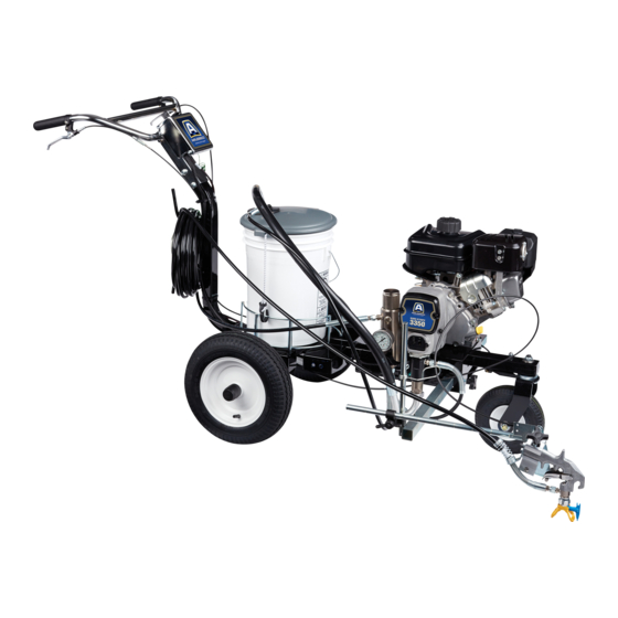
Airless Line Striper
For the application of line striping materials. For professional use only. For outdoor use
only. Not approved for use in explosive atmospheres or hazardous locations.
Model: 25M232
3300 psi (22.8 MPa, 228 bar) Maximum Operating Pressure
Important Safety Instructions
Read all warnings and instructions in this manual, related manuals, and on the
equipment. Be familiar with the controls and the proper usage of the equipment.
Save these instructions.
Related Manuals:
3A4408
Gun
3A4347
Pump
ti30693a
3A4637A
EN
Advertisement
Table of Contents
Troubleshooting

Subscribe to Our Youtube Channel
Related Manuals for AIRLESSCO SURE STRIPE 3350 SP


Summary of Contents for AIRLESSCO SURE STRIPE 3350 SP
- Page 1 Operation, Repair, Parts 3A4637A Airless Line Striper For the application of line striping materials. For professional use only. For outdoor use only. Not approved for use in explosive atmospheres or hazardous locations. Model: 25M232 3300 psi (22.8 MPa, 228 bar) Maximum Operating Pressure Important Safety Instructions Read all warnings and instructions in this manual, related manuals, and on the equipment.
-
Page 2: Table Of Contents
Installation ........35 Airlessco Standard Warranty ..... 72 Pressure Adjust Potentiometer . -
Page 3: Warnings
Warnings Warnings The following warnings are for the setup, use, grounding, maintenance, and repair of this equipment. The exclamation point symbol alerts you to a general warning and the hazard symbols refer to procedure-specific risks. When these sym- bols appear in the body of this manual or on warning labels, refer back to these Warnings. Product-specific hazard sym- bols and warnings not covered in this section may appear throughout the body of this manual where applicable. - Page 4 Warnings EQUIPMENT MISUSE HAZARD Misuse can cause death or serious injury. • Do not operate the unit when fatigued or under the influence of drugs or alcohol. • Do not exceed the maximum working pressure or temperature rating of the lowest rated system component.
- Page 5 Warnings PERSONAL PROTECTIVE EQUIPMENT Wear appropriate protective equipment when in the work area to help prevent serious injury, including eye injury, hearing loss, inhalation of toxic fumes, and burns. This protective equipment includes but is not limited to: • Protective eyewear, and hearing protection. •...
-
Page 6: Uni-Tip Selection
Uni-Tip Selection Uni-Tip Selection (cm) (cm) (cm) (cm) 69215ST* 2 (5) 69217ST 4 (10) 69219ST 4-6 (10-15) 69315ST 6 (15) 69317ST 6 (15) 69319ST 6 (15) 69321ST 6 (15) 69323ST 6-8 (15-20) ... -
Page 7: Component Identification
Component Identification Component Identification 7 8 9 10 PRIME SPRAY ti30694a Spray Gun Trigger Engine Controls Front Wheel Lock/Unlock Filter Drive Control Gauge Drive Motor Prime/Spray Brake Drain Hose Battery Suction Tube Adjustable Handle Speed Control Adjustable Pail Holder Drive Power Switch Pump Pump Switch Trigger Lock... -
Page 8: Grounding Procedure (For Flammable Materials Only)
Grounding Procedure (For Flammable Materials Only) Grounding Procedure 1. Perform Grounding Procedure if using flammable materials. (For Flammable Materials Only) 2. Set pump switch OFF. Turn engine OFF by pressing the engine kill switch at the controls, or by moving the lever on the engine. -
Page 9: Maintenance
Maintenance Maintenance DAILY: Check hose for wear and damage. ANNUALLY: • Replace spark plug. DAILY: Check gun safety for proper operation. • Replace air filter. DAILY: Check pressure drain valve for proper • Replace pre-cleaner. operation. • Service fuel system. DAILY: Check and fill the gas tank. -
Page 10: Operation
Operation Operation Setup 3. Check engine oil level. See Briggs & Stratton engine manual. The equipment must be grounded to reduce the risk of static sparking. Static sparking can cause fumes to ignite or explode. Grounding provides an escape wire for the electric current. -
Page 11: Self-Propelled Drive
Operation Self-Propelled Drive Power ON/OFF The self-propelled drive assists the user in moving the The drive power switch includes the engine kill function. striper through turf and/or up a grade. The drive can be used with or without the engine running. Maximum performance 1. -
Page 12: Drive Control
Operation Drive Control Speed Control The drive control switch on the left handlebar has three 1. With the engine already running, and the drive positions to control the engagement of the drive system. system OFF, turn the speed knob fully counterclockwise to the “0”... -
Page 13: Startup
Operation Startup 4. Turn pressure control counterclockwise to lowest pressure. 1. Perform Grounding Procedure (For Flammable Materials Only), page 8. ti30378a 2. Place siphon tube set in grounded metal pail partially filled with flushing fluid. Attach ground wire to pail and 5. - Page 14 Operation 8. Start Engine. d. Pull starter cord. a. Move fuel valve to open. ti29100a ti29206b e. After engine starts, move choke to open. b. Move choke to closed. ti29210b Set throttle to slow. ti29207b c. Set throttle to fast. ti29211b ti29208b NOTICE...
- Page 15 Operation 9. Set pump switch to ON. Increase pressure enough 12. Inspect fittings for leaks. Do not stop leaks with your to start pump. Allow fluid to circulate for 15 seconds. hand or a rag! If leaks occur, turn striper OFF imme- diately.
-
Page 16: Uni-Tip And Guard Assembly
Operation Uni-Tip and Guard Assembly 3. Screw assembly onto gun. Hand tighten. To avoid serious injury from skin injection do not put your hand in front of the spray tip when installing or removing the spray tip and tip guard. To prevent spray tip leaks, make certain spray tip and tip guard are installed properly. -
Page 17: Gun Placement
Gun Placement Gun Placement 3. Position gun left/right. Install Gun 1. Insert gun into gun holder with hose guard pressed against the holder assembly bracket. Tighten gun into clamp. ti30095a a. Right-side gun position: Place gun and related hardware on right-hand side. ti30093a Position Gun 2. - Page 18 Gun Placement b. Left-side gun position: Place gun and related 5. For Gun Arc Spray Position, place gun at rear of striper. Rear position improves arc quality. hardware on left-hand side. ti30099a NOTE: Verify that the gun can still be triggered and that the trigger lock can still be engaged after installation.
-
Page 19: Paint Stripe Width
Paint Stripe Width Paint Stripe Width 1. Adjust gun up or down to change paint stripe width. 2. Trigger gun and spray test pattern. Slowly adjust pressure to eliminate heavy edges. Use smaller tip size if pressure adjustment can not eliminate heavy edges. -
Page 20: Clean-Up
Clean-up Clean-up 5. Remove siphon tube set from paint and place in flushing fluid. Use water or pump conditioner for water-base paint and mineral spirits for oil-base paint. 1. Perform Pressure Relief Procedure, page 8. 2. Remove Uni-Tip Guard and Uni-Tip. ti30112a 6. - Page 21 Clean-up 8. Hold gun against paint pail. Disengage gun trigger 11. Open prime valve and allow flushing fluid to circu- lock. late for 20 seconds to clean drain tube. ti30118a NOTICE ti30115a Do not run pump without fluid flow. Damage to packings can occur.
- Page 22 Clean-up 15. Install filter into filter bowl. Make sure plastic center NOTICE tube is tightened securely. If flushing with water, do not leave water in sprayer for extended periods. Flush again with pump conditioner and leave protective coating in the sprayer to prevent freezing or corrosion and to increase sprayer life.
-
Page 23: Flushing Recommendations
Flushing Recommendations Flushing Recommendations If you are going to: Flush with: Prime with: Clean with: Store with: Compatible paint, Compatible solvent such Spray with new sprayer or Compatible solvent such as Mineral such as water-base as water or mineral sprayer that has been stored water or mineral spirits spirits or oil-base... -
Page 24: Troubleshooting
Troubleshooting Troubleshooting Problem Cause Solution Engine won’t start Engine is out of gas Refill gas tank. Briggs & Stratton Owner’s Manual. Engine oil level is low Check oil level. Replenish oil, if necessary. Briggs & Stratton Owner’s Manual. Spark plug is disconnected or damaged Connect spark plug cable or replace spark plug. - Page 25 Troubleshooting Problem Cause Solution Pump output is low Strainer is clogged Clean strainer. See pump manual. Piston ball is not seating Service piston ball. See pump manual. Piston packings are worn or damaged Replace packings. See pump manual. O-ring in pump is worn or damaged Replace o-ring.
-
Page 26: Displacement Pump
Displacement Pump Displacement Pump Removal 5. Loosen jam nut by hitting firmly with a hammer. Unscrew pump. 1. Stop pump with piston rod (29) in its lowest position. 2. Perform Pressure Relief Procedure, page 8. 3. Loosen two screws (32) and remove pump rod cover (107). -
Page 27: Installation
Displacement Pump Installation 3. Screw jam nut down onto pump until nut stops. Screw pump up into drive housing until top threads of pump are flush with drive housing face. Back off pump and jam nut to align pump outlet to side. Tighten jam nut by hand, then tap 1/8 to 1/4 turn with a 20 oz (maximum) hammer to approximately If pin works loose, parts could break off due to force... -
Page 28: Drive Housing And Connecting Rod
Drive Housing and Connecting Rod Drive Housing and Connecting Rod Removal NOTICE DO NOT use drive housing screws (34) to align or seat bearing housing with drive housing. Align these parts with locating pins to avoid premature bearing wear. 7. Install screws (34) in drive housing. Torque evenly to 1. -
Page 29: Pinion Assembly/Clutch Armature/Clamp
Pinion Assembly/Clutch Armature/Clamp Pinion Assembly/Clutch Armature/Clamp Pinion Assembly/Clutch 5. Remove four screws (42) and lock washers (35). Install two screws in threaded holes (E) in rotor. Armature Removal Alternately tighten screws until rotor comes off. Pinion Assembly If pinion assembly (44) is not removed from clutch housing (45), do 1. -
Page 30: Installation
Pinion Assembly/Clutch Armature/Clamp Clutch Armature Pinion Assembly 8. Use an impact wrench or wedge something 1. Check o-ring (44e) and replace if missing or between clutch armature (39) and clutch housing to damaged. hold engine shaft during removal. 2. Tap pinion shaft (44c) in with plastic mallet. 9. -
Page 31: Clamp Removal
Pinion Assembly/Clutch Armature/Clamp Clamp Removal 1. Remove engine. See Engine Removal, page 33. 4. Loosen two screws (36) on clamp (38). 2. Drain gasoline from tank according to Briggs & 5. Push screwdriver into slot in clamp (38) and remove Stratton manual. -
Page 32: Clutch Housing
Clutch Housing Clutch Housing Removal Installation 1. Remove clamp. Perform Clamp Removal, page 31. 1. Push on clutch housing (45). 2. Remove four screws (51) and lock washers (50) that 2. Install four cap screws (51) and lock washers (50) hold clutch housing (45) to engine. -
Page 33: Engine
Engine Engine Removal NOTE: All service to the engine must be performed by a Briggs & Stratton authorized service dealer. 1. Disconnect all necessary wiring. 2. Remove two lock nuts (111) and screws (110) from base engine, and screw (145) from clutch housing (45) 3. -
Page 34: Pressure Control Transducer
Pressure Control Transducer Pressure Control Transducer Removal Installation 1. Remove two screws (32) and open cover (62a). 1. Install o-ring (99) and transducer (155) in filter hous- ing (67). Torque to 35 - 45 ft-lb. 2. Disconnect transducer (155) cable from control board (62e). -
Page 35: Pressure Control (On/Off Switch)
Pressure Control (On/Off Switch) Pressure Control (On/Off Switch) Removal Installation 1. Remove two screws (32) and open cover (62a). 1. Install new ON/OFF switch (62d) so tabs of switch snap into place on inside of cover. 2. Disconnect ON/OFF switch connector from pres- sure control board (342). -
Page 36: Pressure Adjust Potentiometer
Pressure Adjust Potentiometer Pressure Adjust Potentiometer Removal Installation 1. Remove two screws (32) and open cover (62a). 1. Install spacer (62g) on potentiometer (62b). 2. Disconnect potentiometer (62b) cable from control 2. Install potentiometer, shaft nut, lock washer and board (62e). potentiometer knob (62c). -
Page 37: Battery
Battery Battery Removal 3. Unscrew M5 terminal screws (358) to disconnect battery from wire harness. 1. Shut off engine, turn off the self-propelled drive system, switch to neutral and engage the parking brake. Neutral ti30424a 4. Remove battery (321) from bracket (320). ti30421a 2. -
Page 38: Installation
Drive Motor Drive Motor Installation 1. Place battery (321) into bracket (320) and connect the red wire to the positive terminal and the black wire to the negative terminal. NOTICE Removal DO NOT reverse the positive and negative battery wires. This will damage the motor control board. - Page 39 Drive Motor 3. Remove the rear chain guard (318). 5. Loosen the two bolts (314) that secure the motor mount to the frame and slide the motor completely forward to loosen the chain (316). Loosen the two set screws on the motor sprocket (313). ti30428a 4.
-
Page 40: Installation
Drive Motor Installation 3. Slide the motor bracket (310) back to leave about 1/8” slack in the chain (316), and tighten the motor mount bolts (314). Torque to 30-40 ft-lb (41-54 N·m). 1. Place a drop of blue thread locking liquid on the threads of each of the four M6 motor screws (312). - Page 41 Drive Motor 4. Adjust the motor sprocket (313) so that it is in-line with 6. Reconnect the battery (321) or replace the fuse. Turn the axle sprocket, then place a drop of blue thread ON the self-propelled drive. With the brake ON and locking liquid onto the threads of each set screw and the right wheel securely elevated just enough to be off secure the motor sprocket in place.
-
Page 42: Drive Wheels
Drive Wheels Drive Wheels Removal 3. While holding the wheel (3) to keep the axle from spinning, loosen and remove the axle nut (307). Slide the wheel off the axle (300) making sure to retain the key (306). 1. Shut off engine and turn off the self-propelled drive system and switch to neutral. -
Page 43: Drive Switch
Drive Switch Drive Switch Removal 4. Remove the strain relief bushing (333) and disconnect the blue wire from (-A) on the control board and from the blue motor wire. Disconnect the 1. Shut off engine, turn off self-propelled drive system, white wire from (HI) on the control board (62e) and switch to neutral and engage the parking brake. -
Page 44: Installation
Drive Switch Installation 4. Replace the strain relief bushing (333) and close control box cover (62a). 1. Install the switch into the housing and connect the wire harness to the switch. ti30696a 5. With the self-propelled drive system switch in the OFF position, and the drive switch in “N”, connect the battery or insert the fuse. -
Page 45: Drive/Axle Bearings
Drive/Axle Bearings Drive/Axle Bearings Removal 3. While holding the wheel (3) to keep the axle (300) from spinning, loosen and remove the axle nut (307). Slide the wheel off the axle making sure to retain the key (306). 1. Shut off the engine and turn off the self-propelled drive system and switch to neutral. -
Page 46: Installation
Drive/Axle Bearings 6. Remove the axle bracket nuts (309) and bolts (308) to 8. If replacing the axle bearings, unbolt each bearing disconnect the axle assembly from the striper frame. (304 and 305) from the axle bracket (302). ti30461a Installation 1. - Page 47 Drive/Axle Bearings 3. Bolt the axle assembly to the frame and torque to 6. Wrap the chain (316) around the axle and motor 30-40 ft-lb (40.7-54.2 N·m). sprockets and reconnect using the master link. Slight repositioning of the motor may be required. 4.
-
Page 48: Drive Chain
Drive Chain Drive Chain Removal Installation 1. Wrap the chain around the axle and motor sprocket and reconnect using the master link. 1. Shut off the engine, turn off the self-propelled drive system, switch to neutral and engage parking brake. Neutral ti30421a ti30509a... -
Page 49: Motor Control Board
Motor Control Board Motor Control Board Removal 3. Open the control box cover (62a) and carefully disconnect the seven wires that are connected to the male spade terminals and the one white 1. Shut off engine, turn off self-propelled drive system, potentiometer wire. -
Page 50: Installation
Motor Control Board Installation NOTICE DO NOT reverse the positive and negative battery wires. 1. Locate control board (62e) on the four threaded studs in This will damage the motor control board. control box cover (62a) and secure using four mounting nuts (62f) torqued to 16-20 in-lb (1.8-2.3 N·m). -
Page 51: Speed Control
Speed Control Speed Control Removal 3. Remove the speed knob (62h) using a 5/64” allen wrench, the friction o-ring (62k), the retaining nut, and the spacer (62g). 1. Shut off engine, turn off self-propelled drive system, switch to neutral and engage parking brake. Neutral ti30421a 2. -
Page 52: Installation
Speed Control Installation 3. Reconnect the three speed control wires. White to the other white wire, orange to “LO,” and red to “WP”. 1. Slide the rubber spacer (62g) onto the speed poten- tiometer, insert the potentiometer into the hole in the cover (62a), and secure using the retaining nut torqued to 8-11 in-lb (0.9-1.2 N·m), then slide the friction o-ring (62k) onto the stud. -
Page 53: Troubleshooting - Drive System
Troubleshooting - Drive System Troubleshooting - Drive System Does not Drive Step 1: Turn Drive System switch to ON (down position). Drive System turned ON? Green LED should illuminate indicating drive is powered. Green LED on motor control board also indicates board is powered. With switch set to cruise ( ), slowly turn Speed Control knob Step 2: Speed knob turned... -
Page 54: Fluid Pump Runs Constantly
Troubleshooting - Drive System Fluid Pump Runs Constantly 1. Perform Pressure Relief Procedure, page 8, turn prime valve forward to SPRAY position, and turn power switch OFF. 2. Remove control box cover. Troubleshooting Procedure: With a pressure gauge plumbed into Pump problem. -
Page 55: Control Board Malfunction
Troubleshooting - Drive System Control Board Malfunction Troubleshooting Procedure (see following page for actual steps): Remove control box cover. Turn sprayer ON. Observe control board Green and Red LED Lights. Go to step 1. Replace the No light Does switch switch. -
Page 56: Control Board Malfunction (Steps)
Troubleshooting - Drive System Control Board Malfunction (Steps) STEP 3. STEP 2. STEP 1. 10-12 DC Leave engine Turn engine Turn 12 -20 AC BEEP running and ON. Set engine turn switch meter to AC OFF and ON. Turn volts and set meter potentiometer connect wires... -
Page 57: Pump Control Status Led
Troubleshooting - Drive System Pump Control Status LED LED Status SPRAYER OPERATION INDICATION ACTION Red LED Power is applied. (Pressure Normal operation. Spray varies with tip size and 1 blink at power up pressure control setting). Red LED Sprayer won’t run. Pump won’t cycle. -
Page 58: Parts Drawing
Parts Drawing Parts Drawing 25M232 86 150 ti30697a 3A4637A Operation, Repair, Parts... -
Page 59: Parts List - 25M232
Parts List - 25M232 Parts List - 25M232 Ref. Part Description Ref. Part Description 100731 WASHER 17N511 FRAME 17N715 LABEL, SS 3350SP 119542 WHEEL, small 144 194126 LABEL, warning 17N070 WHEEL, large 150 16P136 LABEL, safety, warning 17N149 FORK, painted 111025 GASKET, polypropylene 119532 BEARING, flanged 117727 CLIP, wire... -
Page 60: Parts Drawing
Parts Drawing Parts Drawing Self-Propelled Drive ti30602a 3A4637A Operation, Repair, Parts... -
Page 61: Parts List - Self-Propelled Drive
Parts List - Self-Propelled Drive Parts List - Self-Propelled Drive Ref. Part Description Ref. Part Description 129467 SPROCKET, 12 tooth 17N475 AXLE, self-propelled 120229 SCREW, hex, flange 17N316 SPACER, unthreaded 17P355 BRACE, motor bracket, painted 17N662 BRACKET, axle 129466 CHAIN, roller, #40 129437 BEARING, flange, 2 bolt 17P356 BRACKET, chain guard 129465 BOLT, carriage... -
Page 62: Parts Drawing
Parts Drawing Parts Drawing 44ref 130ref ti30132a 3A4637A Operation, Repair, Parts... -
Page 63: Parts List - 25M232
Parts List - 25M232 Parts List - 25M232 Ref. Part Description Ref. Part Description 107434 BEARING, thrust 16D576 LABEL, made in USA 100214 WASHER, lock 17M989 PUMP, displacement 108842 SCREW, cap, hex hd 196750 SPRING, retaining 277019 COVER, front, includes 32 287053 ROD, connecting 56†... -
Page 64: Parts Drawing And List - Pinion Housing
Parts Drawing and List - Pinion Housing Parts Drawing and List - Pinion Housing Ref No. 44: Pinion Housing Ref. Part Description 17R785 HOUSING, pinion, kit 17R793 KIT, repair, coil 105489 44c* 17R788 PINION SHAFT 44d* 113094 RETAINING RING, large 44e* 165295 O-RING, packing * May be ordered separately... -
Page 65: Gun Arm Parts
Gun Arm Parts Gun Arm Parts 72ref ti30135a Part Description Part Description 15E992 CABLE, gun 25M223 GUN, SureStripe 119648 SCREW, mach, trusshd, cross 15F216 HOLDER, gun recess 20a* 15F750 HOLDER, gun, knob 113428 SCREW, cap, socket, flthd 20b* 15F214 LEVER, actuator 188135 GUIDE, cable 20c* 15F209... -
Page 66: Pressure Control/Filter Assembly
Pressure Control/Filter Assembly Pressure Control/Filter Assembly 62f 62e 361 332 ref. 74 ref. 59 ti30520a ref 13 141ref 118ref 18ref 75ref ti30134a 3A4637A Operation, Repair, Parts... -
Page 67: Parts List - Pressure Control/Filter Assembly
Parts List - Pressure Control/Filter Assembly Parts List - Pressure Control/Filter Assembly Part Description Part Description 237686 WIRE, ground, assembly w/ 108538 SCREW, cap, flat hd clamp 194310 LEVER, actuator 15F928 BUSHING, strain relief 24Z793 COVER, control box, assy 152* 15G331 PIPE, plug, sst 17N544 COVER, control box 155* 15F782... -
Page 68: Pressure Control Wiring Diagram
Pressure Control Wiring Diagram Pressure Control Wiring Diagram ENGINE REGULATOR RECTIFIER SPEED DRIVE ON/OFF 324ref (15a) JUMPER CONTROL ENGINE KILL ADAPTER BLACK YELLOW YELLOW BLACK BLACK BLACK BATTERY FUSE ORANGE BLACK — RED + MOTOR CONTROL BOARD CONTROL BOARD WHITE WHITE BLUE TRANSDUCER... -
Page 69: Drive Control Wiring Diagram
Drive Control Wiring Diagram Drive Control Wiring Diagram ENGINE REGULATOR SPEED DRIVE ON/OFF RECTIFIER CONTROL ENGINE KILL (15a) FUSE BLACK BLACK ORANGE BATTERY FRAME MOTOR CONTROL BOARD DRIVE MOTOR BLACK WHITE WHITE BLUE FERRITE SUPPRESSOR (359) WIRE HARNESS CRUISE-NEUTRAL-DRIVE (328) SWITCH ti30700a 3A4637A Operation, Repair, Parts... -
Page 70: Technical Data
Technical Data Technical Data Sure Stripe 3350SP (Model 25M232) Metric Briggs & Stratton Vanguard™ Model 130000 SAE J1995 @ 3600 rpm 5.5 Horsepower Maximum working pressure 3300 psi 22.8 MPa, 228 bar Maximum delivery 0.75 gpm 2.84 lpm Maximum tip size 1 gun with 0.027 in. -
Page 71: Notes
Notes Notes 3A4637A Operation, Repair, Parts... -
Page 72: Airlessco Standard Warranty
With the exception of any special, extended, or limited warranty published by Airlessco, Airlessco will, for a period of twelve months from the date of sale, repair or replace any part of the equipment determined by Airlessco to be defective.
Need help?
Do you have a question about the SURE STRIPE 3350 SP and is the answer not in the manual?
Questions and answers