Table of Contents
Advertisement
Quick Links
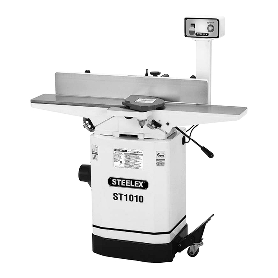
MODEL ST1010
6" JOINTER W/ MOBILE BASE
OWNER'S MANUAL
For manuals manufactured since 03/16
Phone: (360) 734-3482 • Online Technical Support: techsupport@woodstockint.com
COPYRIGHT © APRIL, 2016 BY WOODSTOCK INTERNATIONAL, INC., REVISED MARCH, 2017 (HE)
WARNING: NO PORTION OF THIS MANUAL MAY BE REPRODUCED IN ANY SHAPE OR FORM WITHOUT
THE WRITTEN APPROVAL OF WOODSTOCK INTERNATIONAL, INC.
#17980MC
V2.03.17
Printed in China
Advertisement
Table of Contents

Related Manuals for Steelex ST1010


Summary of Contents for Steelex ST1010
- Page 1 MODEL ST1010 6" JOINTER W/ MOBILE BASE OWNER'S MANUAL For manuals manufactured since 03/16 Phone: (360) 734-3482 • Online Technical Support: techsupport@woodstockint.com COPYRIGHT © APRIL, 2016 BY WOODSTOCK INTERNATIONAL, INC., REVISED MARCH, 2017 (HE) WARNING: NO PORTION OF THIS MANUAL MAY BE REPRODUCED IN ANY SHAPE OR FORM WITHOUT THE WRITTEN APPROVAL OF WOODSTOCK INTERNATIONAL, INC.
- Page 2 This manual provides critical safety instructions on the proper setup, operation, maintenance and service of this machine/equipment. Failure to read, understand and follow the instructions given in this manual may result in serious personal injury, including amputation, electrocution or death. The owner of this machine/equipment is solely responsible for its safe use.
-
Page 3: Table Of Contents
INTRODUCTION ............ 2 ACCESSORIES ............32 MAINTENANCE ............ 34 Contact Info ..............2 Manual Accuracy ............2 General ................34 Model ST1010 Machine Specifications ....3 Cleaning .................34 Machine Features ............5 Lubrication ..............34 Controls & Components ..........6 Maintenance Schedule ..........34 SAFETY .............. -
Page 4: Introduction
INTRODUCTION Contact Info Manual Accuracy We are committed to customer satisfaction. If you We are proud to provide a high-quality owner’s have any questions or need help, use the information manual with your new machine! below to contact us. We made every effort to be exact with the instruc- IMPORTANT: Before contacting, please get the tions, specifications, drawings, and photographs original purchase receipt, serial number, and... -
Page 5: Model St1010 Machine Specifications
Type.................................... TEFC Capacitor-Start Induction Horsepower ..........................................1 HP Phase ..........................................Single-Phase Amps ..............................................13A Speed ........................................... 3450 RPM Power Transfer .......................................V-Belt Drive Bearings ................................Sealed & Permanently Lubricated Model ST1010 Machine Specifications, Page 1 of 3 ST1010 6" Jointer (Mfd. Since 3/16) - Page 6 Guard ......................................Die Cast Metal Table ..................................Precision-Ground Cast Iron Paint Type/Finish ..................................Powder Coated Other Information Number of Dust Ports ......................................1 Dust Port Size ........................................4 in. ST1010 6" Jointer (Mfd. Since 3/16) Model ST1010 Machine Specifications, Page 2 of 3...
-
Page 7: Machine Features
POWER Indicator Outfeed Table Light Depth Scale Outfeed Table Handwheel Infeed Table Infeed Table Height Lever Dust Port Locking Foot Pedal To reduce your risk of serious injury, read this entire manual BEFORE using machine. ST1010 6" Jointer (Mfd. Since 3/16) -
Page 8: Controls & Components
Outfeed Table Handwheel: Adjusts position of outfeed table. Only used when setting outfeed table even with cutterhead knives. Depth Scale Outfeed Table Handwheel Infeed Table Lever Figure 2. Table movement controls. ST1010 6" Jointer (Mfd. Since 3/16) -
Page 9: Safety
Everyday eyeglasses Never operate under the influence of drugs or alco- are NOT approved safety glasses. hol, when tired, or when distracted. ST1010 6" Jointer (Mfd. Since 3/16) - Page 10 Make sure they are properly installed, undamaged, EXPERIENCING DIFFICULTIES. If at any time you and working correctly BEFORE operating machine. experience difficulties performing the intended oper- ation, stop using the machine! Contact our Technical Support at (570) 546-9663. ST1010 6" Jointer (Mfd. Since 3/16)
-
Page 11: Additional Safety For Jointers
GRAIN DIRECTION. Jointing against the grain or end (0.125") from cutterhead body. grain can increase the risk of kickback. It also requires more cutting force, which produces chatter or exces- sive chip out. Always joint or surface plane WITH the grain. ST1010 6" Jointer (Mfd. Since 3/16) -
Page 12: Electrical
To reduce this risk, only an electrician or qualified service person- nel should do any required electrical work on this machine. -10- ST1010 6" Jointer (Mfd. Since 3/16) -
Page 13: Grounding Requirements
Grounding Prong receptacle, and meet the following requirements: Minimum Gauge Size ........ 12 AWG Maximum Length (Shorter is Better) ....50 ft. 5-15 PLUG Neutral Hot Figure 4. Typical 5-15 plug & receptacle. -11- ST1010 6" Jointer (Mfd. Since 3/16) -
Page 14: Setup
When you are completely satisfied with the condition of your shipment, you should inventory the contents. SUFFOCATION HAZARD! Immediately discard all plas- tic bags and packing materi- als to eliminate choking/suf- focation hazards for children and animals. -12- ST1010 6" Jointer (Mfd. Since 3/16) -
Page 15: Inventory
Hold Downs (Switch) ..........2 these locations before assuming that any items • Phillips Screw M6-1 x 12 (Handwheel) ....1 from the inventory list are missing. • Flat Washer 6mm (Handwheel) ......1 -13- ST1010 6" Jointer (Mfd. Since 3/16) -
Page 16: Hardware Recognition Chart
25mm Flat 30mm Head 35mm Screw Bolt Screw Screw 40mm 10mm 45mm 50mm 55mm 12mm Lock Internal 60mm External E-Clip Wrench Retaining Retaining 65mm Ring Ring 70mm 75mm 16mm Lock Flat Washer Washer -14- ST1010 6" Jointer (Mfd. Since 3/16) -
Page 17: Cleanup
Repeat Steps 2–3 as necessary until clean, then coat all unpainted surfaces with a quality metal protectant to prevent rust. -15- ST1010 6" Jointer (Mfd. Since 3/16) -
Page 18: Site Considerations
Only install in an access restricted location. Wall Min. 30" for Maintenance 46" 120V " = Electrical Connection Figure 7. Working clearances. -16- ST1010 6" Jointer (Mfd. Since 3/16) -
Page 19: Assembly
10. Align the three mounting bolt holes on the jointer with the three holes on the cabinet (see Figure 11). Mounting Holes Figure 9. Installing locking foot pedal. Figure 11. Mounting holes. -17- ST1010 6" Jointer (Mfd. Since 3/16) - Page 20 15. Looking from the top, sight down the V-belt and pulleys and check to see that the pulleys are Figure 15. Locating pins. parallel and aligned with each other (see Figure 14). -18- ST1010 6" Jointer (Mfd. Since 3/16)
- Page 21 22. Use (2) M8-1.25 x 25 cap screws, (2) 8mm lock washers, and (2) 8mm flat washers to secure the fence assembly to the fence carriage assembly (see Figure 18). Figure 20. Cutterhead guard set screw location. Figure 18. Installing fence assembly. -19- ST1010 6" Jointer (Mfd. Since 3/16)
- Page 22 Explaining this calculation is beyond the scope of this manual. If you are unsure of your system, Set Screw consult an expert or purchase a good dust collection "how-to" book. Figure 22. Reinstalling set screw. -20- ST1010 6" Jointer (Mfd. Since 3/16)
- Page 23 Hold Downs Motor Cord Figure 27. Installing infeed table lever. 35. Tighten the locknut. Figure 25. Cord locations. 32. Remove the Phillips head screw and flat washer already mounted to the handwheel shaft. -21- ST1010 6" Jointer (Mfd. Since 3/16)
-
Page 24: Setting Outfeed Table Height
38. Raise or lower the outfeed table until the knife just touches the straightedge (see Figure 29). Straightedge Outfeed Infeed Figure 29. Using a straightedge to align outfeed table height with knife at TDC. -22- ST1010 6" Jointer (Mfd. Since 3/16) -
Page 25: Test Run
Step-by-step instructions for these adjustments can be found in SERVICE. Factory adjustments that should be verified: Knife Settings (Page 37). Depth Scale Calibration (Page 38). Fence Stop Accuracy (Page 39). -23- ST1010 6" Jointer (Mfd. Since 3/16) -
Page 26: Operations
If you have never used this type of machine 10. Stops jointer. or equipment before, WE STRONGLY RECOM- MEND that you read books, trade magazines, or get formal training before beginning any projects. -24- ST1010 6" Jointer (Mfd. Since 3/16) -
Page 27: Stock Inspection And Requirements
• sure that any stock you process with the jointer is clean and free of any dirt, nails, staples, tiny rocks or any other foreign objects that may dam- age the jointer blades. -25- ST1010 6" Jointer (Mfd. Since 3/16) -
Page 28: Infeed Table Adjustment
To adjust the infeed table: Loosen the infeed table lock in Figure 35. Table Stop Lock Nuts Figure 36. Adjusting infeed table height. Infeed Table Lock Figure 35. Infeed table lock. -26- ST1010 6" Jointer (Mfd. Since 3/16) -
Page 29: Squaring Stock
(see Figure 38). Previously Jointed Edge Figure 40. Rip-cut on a table saw. Previously Surface Planed Face Figure 38. Surface plane on a thickness planer. -27- ST1010 6" Jointer (Mfd. Since 3/16) -
Page 30: Surface Planing
If your workpiece is cupped (warped), place it so the concave side is face down on the surface of the infeed table. Turn jointer ON. Removed Surface Figure 42. Illustration of surface planing results. -28- ST1010 6" Jointer (Mfd. Since 3/16) -
Page 31: Edge Jointing
Always use push blocks to protect your hands when surface planing on the jointer. Removed Surface Figure 43. Illustration of edge jointing results. -29- ST1010 6" Jointer (Mfd. Since 3/16) -
Page 32: Bevel Cutting
(see Figures 45 & 46). Note: If your leading hand gets within 4" of the The Model ST1010 has preset fence stops at 45˚ cutterhead, lift it up and over the cutterhead, inward, 90˚, and 45˚ outward (135˚). If your situation... -
Page 33: Rabbet Cutting
ALWAYS replace cutterhead guard after rabbet cutting! Figure 49. Illustration of rabbet cutting effects and a few sample joints. -31- ST1010 6" Jointer (Mfd. Since 3/16) -
Page 34: Accessories
± 0.0006". Figure 52. Model W1216A Planer Pal. Figure 50. D3833 4" Precision squares. The W1211A Jointer Pal® Steel Body Jig (ST1010) is Our W1400 Small Push Blocks are constructed a patented jointer knife-setting jig for perfect align-... - Page 35 Mounting screws are not included. Figure 54. D1123 Knife Honer. The D3637 6" HSS Jointer Knives (Set of 4) are the replacement blades for the Steelex ST1010. Figure 56. Model D4028 8" Digital Scale. The Model D4042 6" Digital Caliper lets you switch between decimal and fractional inches and millim- eters.
-
Page 36: Maintenance
Vacuum all dust on and around the machine. • Wipe down tables and all other unpainted Cleaning the Model ST1010 is relatively easy. Vacuum cast- iron with a metal protectant. excess wood chips and sawdust, and wipe off the remaining dust with a dry cloth. If any resin has built Every Month: up, use a resin-dissolving cleaner to remove it. -
Page 37: Service
(Page 37). 7. Cutterhead bearings at fault. 7. Replace bearing(s)/realign cutterhead. 8. Centrifugal switch at fault. 8. Replace. 9. Test by rotating shaft; rotational grinding/loose shaft 9. Motor bearings at fault. requires bearing replacement. -35- ST1010 6" Jointer (Mfd. Since 3/16) - Page 38 2. Workpiece too uneven at start of operation. 2. Take partial cuts to remove extreme high spots before doing a full pass. 3. Outfeed table not parallel with infeed table. 3. Check/Adjust table parallelism. -36- ST1010 6" Jointer (Mfd. Since 3/16)
-
Page 39: Inspecting Knives
To inspect the knives: set the knives at the correct height. DISCONNECT THE JOINTER FROM THE POWER The Model ST1010 comes with both jack screws SOURCE! and springs to provide you with two options for cutterhead adjustments (see Figure 59). -
Page 40: Calibrating Depth Scale
Repeat this step on the rest of the knives. Figure 62. Depth-of-cut pointer Final tighten each gib bolt. adjusted to "0" position. 10. Adjust the outfeed table to match the new knife heights (see Page 222). -38- ST1010 6" Jointer (Mfd. Since 3/16) -
Page 41: Setting Fence Stops
Adjust the 45˚ inward fence stop bolt until it makes contact with the back of the fence. Retighten the jam nut loosened in Step 3 and recheck. Retighten the jam nut loosened in Step 2 and recheck. -39- ST1010 6" Jointer (Mfd. Since 3/16) -
Page 42: Adjusting Gibs
Figure 68. 45˚ outward fence stop bolt and jam nut. Adjust the 45˚ outward fence stop bolt until it makes contact with the back of the fence. Retighten the jam nut loosened in Step 3 and recheck. -40- ST1010 6" Jointer (Mfd. Since 3/16) -
Page 43: St1010 Electrical Components
ST1010 Electrical Components Power Cord Motor Cord Figure 70. W1745 switch wiring. Figure 71. W1745 junction box wiring. -41- ST1010 6" Jointer (Mfd. Since 3/16) -
Page 44: St1010 Wiring Diagram
White Neutral 120 VAC Green SWITCH 5-15 Plug RECEPTACLE (viewed from behind) CONTROL PANEL Note: Control panel buttons are shown backwards to match orientation on machine. 120V MOTOR Start Capacitor 200MFD 125VAC Ground -42- ST1010 6" Jointer (Mfd. Since 3/16) -
Page 45: Parts
PARTS Base Assembly Breakdown 62-3 62-1 62-2 24-1 24-5 24-3 24-4 24-2 24-7 24-6 24-8 24-9 -43- ST1010 6" Jointer (Mfd. Since 3/16) - Page 46 24-7 XST1010024-7 CONTACT PLATE 20MM 62-1 XST1010062-1 ROD 24-8 XST1010024-8 BALL BEARING 6204ZZ 62-2 XST1010062-2 KNIFE JIG FOOT 24-9 XST1010024-9 BALL BEARING 6204ZZ 62-3 XST1010062-3 E-CLIP 9MM XST1010025 KEY 5 X 5 X 30 -44- ST1010 6" Jointer (Mfd. Since 3/16)
- Page 47 Table Assembly Breakdown -45- ST1010 6" Jointer (Mfd. Since 3/16)
- Page 48 148 XST1010148 GUARD MOUNT COLLAR 198 XST1010198 FENCE BRACKET 149 XST1010149 BUTTON HD CAP SCR M4.-7 X 18 199 XST1010199 ANGLE STOP 150 XST1010150 OUTFEED TABLE 200 XST1010200 FLAT WASHER 10MM 151 XST1010151 BASE -46- ST1010 6" Jointer (Mfd. Since 3/16)
- Page 49 XST1010215 RAM ARM GUARD XST1010234 LOCK WASHER 8MM XST1010216 FLAT WASHER 8MM XST1010235 FLAT WASHER 8MM XST1010217 LOCK WASHER 8MM XST1010237 POWER CORD 14G 3W 72" 5-15P XST1010218 CAP SCREW M8-1.25 X 25 -47- ST1010 6" Jointer (Mfd. Since 3/16)
-
Page 50: Label/Cosmetic Parts
CUTTERHEAD EXPOSURE WARNING LABEL XST1010310 PINSTRIPE TAPE XST1010304 ELECTRICITY LABEL XST1010311 TOUCH-UP PAINT, SHOP FOX BLACK XST1010305 CONTROL PANEL LABEL XST1010312 MODEL NUMBER LABEL XST1010306 EYE/EAR/LUNG HAZARD LABEL XST1010313 READ MANUAL LABEL XST1010307 DISCONNECT POWER LABEL -48- ST1010 6" Jointer (Mfd. Since 3/16) -
Page 51: Warranty
Every effort has been made to ensure that all ® machinery meets high quality and durability standards. We reserve the right to change specifications at any time because of our commitment to continuously improve the quality of our products. -49- ST1010 6" Jointer (Mfd. Since 3/16) -
Page 52: Warranty Registration
_____ Other: How long have you been a woodworker/metalworker? _____ 0-2 Years ____ 2-8 Years ____ 8-20 Years ____ 20+ Years How many of your machines or tools are STEELEX ® _____ 0-2 ____ 3-5 ____ 6-9 ____ 10+ Do you think your machine represents a good value? - Page 53 FOLD ALONG DOTTED LINE Place Stamp Here WOODSTOCK INTERNATIONAL INC. P.O. BOX 2309 BELLINGHAM, WA 98227-2309 FOLD ALONG DOTTED LINE TAPE ALONG EDGES--PLEASE DO NOT STAPLE...
Need help?
Do you have a question about the ST1010 and is the answer not in the manual?
Questions and answers