Table of Contents
Advertisement
Quick Links
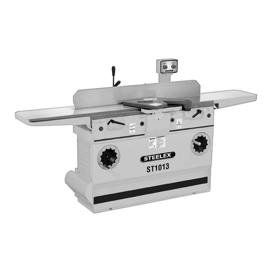
MODEL ST1013
12" JOINTER
OWNER'S MANUAL
(For Models Manufactured Since 03/16)
Phone: (360) 734-3482 • Online Technical Support: techsupport@woodstockint.com
COPYRIGHT © MAY, 2016 BY WOODSTOCK INTERNATIONAL, INC. REVISED JUNE, 2018 (HE)
WARNING: NO PORTION OF THIS MANUAL M PPROVAL OF WOODSTOCK INTERNATIONAL, INC.
#18223MN
V2.06.18
Printed in China
Advertisement
Table of Contents

Related Manuals for Steelex ST1013


Summary of Contents for Steelex ST1013
- Page 1 MODEL ST1013 12" JOINTER OWNER'S MANUAL (For Models Manufactured Since 03/16) Phone: (360) 734-3482 • Online Technical Support: techsupport@woodstockint.com COPYRIGHT © MAY, 2016 BY WOODSTOCK INTERNATIONAL, INC. REVISED JUNE, 2018 (HE) WARNING: NO PORTION OF THIS MANUAL M PPROVAL OF WOODSTOCK INTERNATIONAL, INC.
- Page 2 This manual provides critical safety instructions on the proper setup, operation, maintenance and service of this machine/equipment. Failure to read, understand and follow the instructions given in this manual may result in serious personal injury, including amputation, electrocution or death. The owner of this machine/equipment is solely responsible for its safe use.
-
Page 3: Table Of Contents
Table of Contents INTRODUCTION ............ 2 ACCESSORIES ............28 MAINTENANCE ............ 29 Contact Info ..............2 Manual Accuracy ............2 General ................29 Machine Specifications ..........3 Schedule ................29 Machine Features ............5 Cleaning/Protecting ..........29 Controls & Components ..........6 Lubrication ..............29 SAFETY .............. -
Page 4: Introduction
10. Do not use without dust bag or filters in place. Serial Number 11. Always wear a respirator when emptying bags. 12. Prevent unauthorized use by children or untrained users. Manufactured for Woodstock in Taiwan ST1013 12" Jointer (Mfd. Since 3/16) -
Page 5: Machine Specifications
Maximum Width of Cut .....................................12 in. Maximum Depth of Cut ...................................1/8 in. Minimum Workpiece Length ...................................14 in. Minimum Workpiece Thickness ................................1/2 in. Number of Cuts Per Minute ................................39,600 Model ST1013 Machine Specifications, Page 1 of 2 ST1013 12" Jointer (Mfd. Since 3/16) - Page 6 Spiral Cutterhead with German-Made Indexable Carbide Inserts 3 HP Motor Easy-to-Reach Pedestal-Mounted Control Panel Parallelogram Table Design Allows for Full Adjustability and Calibration Sturdy Cabinet Stand Handwheel-Controlled Table Movement ST1013 12" Jointer (Mfd. Since 3/16) Model ST1013 Machine Specifications, Page 2 of 2...
-
Page 7: Machine Features
Always use hold-down or push blocks when jointing material narrower than 3" or surface planing material thinner than 3". e) Never perform jointing or planing cuts on pieces shorter than 8" in length. ST1013 12" Jointer (Mfd. Since 3/16) -
Page 8: Controls & Components
To adjust the infeed table posi- Figure 4. Fence lock, tilt lock and stop block tive stops, refer to Setting Infeed Table Height on Page 37. locations. Table Locks Table Table Handwheel Handwheel Figure 3. Table control locations. ST1013 12" Jointer (Mfd. Since 3/16) -
Page 9: Safety
Everyday eyeglasses Never operate under the influence of drugs or alco- are NOT approved safety glasses. hol, when tired, or when distracted. ST1013 12" Jointer (Mfd. Since 3/16) - Page 10 Make sure they are properly installed, undamaged, EXPERIENCING DIFFICULTIES. If at any time you and working correctly BEFORE operating machine. experience difficulties performing the intended oper- ation, stop using the machine! Contact our Technical Support at (570) 546-9663. ST1013 12" Jointer (Mfd. Since 3/16)
-
Page 11: Additional Safety For Jointers
" (0.125") from cutterhead body. grain can increase the risk of kickback. It also requires more cutting force, which produces chatter or exces- sive chip out. Always joint or surface plane WITH the grain. ST1013 12" Jointer (Mfd. Since 3/16) -
Page 12: Electrical
Incorrectly wiring grounding this machine can cause electrocution, fire, or machine damage. To reduce this risk, only an electrician or qualified service person- nel should do any required electrical work on this machine. -10- ST1013 12" Jointer (Mfd. Since 3/16) -
Page 13: Grounding Requirements
Figure 5. Typical 6-20 plug and receptacle. The machine must be properly set up before it is safe to operate. DO NOT connect this machine to the power source until instructed to do later in this manual. -11- ST1013 12" Jointer (Mfd. Since 3/16) -
Page 14: Setup
SETUP Unpacking Items Needed for Setup The Model ST1013 was carefully packed when it left our warehouse. If you discover your machine is dam- The following items are needed to complete the set aged immediately call your dealer. up process, but are not included with your machine:... -
Page 15: Inventory
If any parts are missing, find the part number in the back of this manual and contact Woodstock International, Inc. at (360) 734-3482 or at techsupport@woodstockint.com. Figure 8. Assembly hardware. -13- ST1013 12" Jointer (Mfd. Since 3/16) -
Page 16: Hardware Recognition Chart
25mm Flat 30mm Head 35mm Screw Bolt Screw Screw 40mm 10mm 45mm 50mm 55mm 12mm Lock Internal 60mm External E-Clip Wrench Retaining Retaining 65mm Ring Ring 70mm 75mm 16mm Lock Flat Washer Washer -14- ST1013 12" Jointer (Mfd. Since 3/16) -
Page 17: Cleanup
Repeat Steps 2–3 as necessary until clean, then coat all unpainted surfaces with a quality metal protectant to prevent rust. -15- ST1013 12" Jointer (Mfd. Since 3/16) -
Page 18: Site Considerations
Shadows, glare, or strobe effects that may distract or may be seriously injured by this impede the operator must be eliminated. machine. Only install in an access restricted location. Wall 30" Minimum Working Clearance 84" 33" Figure 9. Working clearances. -16- ST1013 12" Jointer (Mfd. Since 3/16) -
Page 19: Lifting & Moving
Lifting & Moving Anchoring to Floor The model ST1013 requires the use of lifting equip- Anchoring machinery to the floor prevents tipping or ment, such as a forklift, engine hoist, or boom crane. shifting and reduces vibration that may occur during DO NOT lift the machine by hand. -
Page 20: Assembly
Remove both M10-1.5 x 25 cap screws and flat washers securing pedestal to jointer base (see Figure 14). Cap Screws Figure 12. Installing fence bracket. Figure 14. Location of pedestal mounting hardware. -18- ST1013 12" Jointer (Mfd. Since 3/16) - Page 21 — If the insert lifts the straightedge off the Bottom Dead table or it is below the straightedge, then the outfeed table must be reset. Refer to Setting Center Outfeed Table Height on Page 37. Figure 16. Adjusting cutterhead guard. -19- ST1013 12" Jointer (Mfd. Since 3/16)
-
Page 22: Dust Collection
Button Figure 19. Dust hose attached to dust port. Figure 20. STOP/START button locations. Tug hose to make sure it does not come off. Note: A tight fit is necessary for proper performance. -20- ST1013 12" Jointer (Mfd. Since 3/16) -
Page 23: Recommended Adjustments
A small amount of black belt dust at the bottom of the belt housing is normal during the life of the machine and does not indicate a problem with the machine or belt. -21- ST1013 12" Jointer (Mfd. Since 3/16) -
Page 24: Operations
OPERATIONS Overview The Model ST1013 will perform many types of opera- Eye injuries or respiratory problems can occur tions that are beyond the scope of this manual. Many while operating this tool. Wear personal pro- of these operations can be dangerous or deadly if tective equipment to reduce your risk from performed incorrectly. -
Page 25: Stock Inspection & Requirements
1" Min. contain asbestos—cutting these materials with a jointer may lead to injury. Figure 23. Minimum stock dimensions for jointer. 10" Min. -23- ST1013 12" Jointer (Mfd. Since 3/16) " Min. -
Page 26: Squaring Stock
(see Figure 25). Previously Jointed Edge Figure 27. Rip-cut on a table saw. Previously Surface Planed Face Figure 25. Surface plane on a thickness planer. -24- ST1013 12" Jointer (Mfd. Since 3/16) -
Page 27: Surface Planing
Figure 29. Illustration of surface planing results. Failure to use push blocks when surface planing could result in your hands contacting rotating cutterhead, which will cause serious personal injury. ALWAYS use push blocks when surface planing on jointer! -25- ST1013 12" Jointer (Mfd. Since 3/16) -
Page 28: Edge Jointing
Figure 31. Illustration of edge jointing results. Tip: When squaring up stock, cut opposite edge of workpiece with a table saw instead of the joint- er—otherwise, both edges of workpiece will not be parallel with each other. -26- ST1013 12" Jointer (Mfd. Since 3/16) -
Page 29: Bevel Cutting
DO NOT let them get closer than 4" from moving cutterhead at any time during operation! Repeat cutting process, as necessary, until you are satisfied with the results. Removed Surface Figure 33. Illustration of bevel cutting results. -27- ST1013 12" Jointer (Mfd. Since 3/16) -
Page 30: Accessories
This product also reduces rust and prevents resin buildup. Figure 40. Model D3379 Indexable Carbide Inserts for Model ST1013. Figure 38. SLIPIT Gel and Spray. ® -28- ST1013 12" Jointer (Mfd. Since 3/16) -
Page 31: Maintenance
Keep the table rust-free with regular applications of a Regular periodic maintenance on your STEELEX ® high-quality metal protectant. Model ST1013 will ensure its optimum performance. Make a habit of inspecting your machine each time Lubrication you use it. Check for the following conditions and repair or... -
Page 32: Maintenance Notes
Maintenance Notes DATE MAINTENTANCE PERFORMED -30- ST1013 12" Jointer (Mfd. Since 3/16) -
Page 33: Service
6. Cutterhead bearings at fault. 6. Replace bearing(s)/re-align cutterhead. 7. Centrifugal switch at fault. 7. Replace. 8. Motor bearings at fault. 8. Test by rotating shaft; rotational grinding/loose shaft requires bearing replacement. -31- ST1013 12" Jointer (Mfd. Since 3/16) - Page 34 2. Workpiece too uneven at start of operation. 2. Take partial cuts to remove extreme high spots before after jointing. doing a full pass. 3. Check/adjust table parallelism (Page 33). 3. Outfeed table not parallel with infeed table. -32- ST1013 12" Jointer (Mfd. Since 3/16)
-
Page 35: Rotating/Replacing Cutterhead Inserts
Remove cutterhead guard from table, and lower infeed and outfeed tables as far as they go to provide access to cutterhead (see Figure 42). Torx Screw Cutterhead Insert Figure 42. Cutterhead inserts and Torx screws. -33- ST1013 12" Jointer (Mfd. Since 3/16) -
Page 36: Checking/Adjusting Table Parallelism
Figure 44 (rotate cutterhead if necessary). Straightedge Outfeed Infeed Figure 44. Adjusting outfeed table even with cutterhead body. -34- ST1013 12" Jointer (Mfd. Since 3/16) - Page 37 Black Lines Represent Straightedge Positions from Overhead View Figure 47. Straightedge positions for checking infeed/outfeed parallelism. -35- ST1013 12" Jointer (Mfd. Since 3/16)
- Page 38 Black Lines Represent Straightedge Positions From Overhead View Figure 49. Straightedge positions for verifying if outfeed table is parallel with cutterhead. -36- ST1013 12" Jointer (Mfd. Since 3/16)
-
Page 39: Setting Outfeed Table Height
Place straightedge on outfeed table so it extends (see Figure 50) so that outfeed table will not over cutterhead. move during operation. Re-install cutterhead guard, fence, and cabinet rear access panel. -37- ST1013 12" Jointer (Mfd. Since 3/16) -
Page 40: Setting Infeed Table Height
Calibrating Depth Height Scale The infeed table on the Model ST1013 has positive The depth-of-cut scale can be calibrated or "zeroed" stop bolts that, when properly set up, allow the oper- to make sure the cutting depth shown on the scale ator to quickly adjust the infeed table between finish/ matches the actual cutting depth (per pass). -
Page 41: Setting Fence Stops
Figure 57. 45˚ inward positive stop bolt. Adjust 45˚ outward positive stop bolt until fence is exactly 45° outward while resting on bolt (check angle with sliding bevel set to 135°). Retighten jam nut loosened in Step 2. -39- ST1013 12" Jointer (Mfd. Since 3/16) -
Page 42: Tensioning/Replacing V-Belt
Figure 60. Fasteners to be loosened for V-Belt replacement. Lift motor up and slide V-belts off of motor pul- ley and cutterhead pulley. Slide new belts onto pulleys and lightly tighten motor bracket fasteners. -40- ST1013 12" Jointer (Mfd. Since 3/16) -
Page 43: Pulley Alignment
V-belts should be parallel and aligned as shown in Figure 62. Bearing Set Screws Block Close pulley cover and re-install belt guard. Cutterhead Cutterhead Pulley Motor Pulley Set Screws Figure 62. Pulleys aligned. -41- ST1013 12" Jointer (Mfd. Since 3/16) -
Page 44: Electrical Components
Electrical Components STOP/Reset ON Switch Switch Figure 64. Motor junction box. Figure 65. Control panel. To Control Panel Contactor Thermal Overload Relay To Motor To Power Source Figure 66. Magnetic switch assembly. -42- ST1013 12" Jointer (Mfd. Since 3/16) -
Page 45: Wiring Diagram
6-20 Plug BLUE (As Recommended) CONTROL Ground PANEL 13no (from behind) Contactor 14no Thermal Overload Ground MAGNETIC SWITCH ASSEMBLY Start Capacitor Ground 200MFD 250VAC 230V Capacitor 20MFD MOTOR 450VAC -43- ST1013 12" Jointer (Mfd. Since 3/16) -
Page 46: Parts
PARTS Base 142-1 142-2 -44- ST1013 12" Jointer (Mfd. Since 3/16) - Page 47 SET SCREW M6-1 X 8 XST1013180 COMBO WRENCH 17/19MM XST1013141 ECCENTRIC BUSHING XST1013181 COMBO WRENCH 12/14MM XST1013142 SHAFT XST1013182 COMBO WRENCH 10/12MM 142-1 XST1013142-1 TORSION SPRING (LEFT) XST1013188 PUSH BLOCK 142-2 XST1013142-2 TORSION SPRING (RIGHT) -45- ST1013 12" Jointer (Mfd. Since 3/16)
-
Page 48: Tables
CAP SCREW M6-1.0 X 10 XST1013207 TABLE LIP (RIGHT) XST1013217 CHIP DEFLECTOR XST1013208 CAP SCREW M10-1.5 X 35 XST1013218 CAP SCREW M5-.8 X 25 XST1013209 LOCK WASHER 10MM XST1013219 STOP BLOCK XST1013210 TABLE EXTENSION -46- ST1013 12" Jointer (Mfd. Since 3/16) -
Page 49: Fence
HEX NUT M8-1.25 XST1013320 HANDLE ROD XST1013341 RIGHT BRACKET XST1013321 HANDLE XST1013342 HEX NUT M8-1.25 XST1013322 SLIDING BUSHING ASSY XST1013343 HEX BOLT M8-1.25 X 35 XST1013323 FLAT WASHER 12MM XST1013345 RIVET 2 X 5 -47- ST1013 12" Jointer (Mfd. Since 3/16) -
Page 50: Stand
Stand 415-2 415-4 415-8 415-10 415-6 415-3 415-5 415-7 415-9 401-1 401-2 415-1 401-1 401-2 434-1 434-3 434-5 434-4 434-2 -48- ST1013 12" Jointer (Mfd. Since 3/16) - Page 51 PULLEY COVER LOCK KNOB XST1013450 FOLDING HANDLE XST1013422 BUTTON HD CAP SCR M6-1 X 18 XST1013451 KEY 5 X 5 X 20 XST1013423 RIGHT ACCESS DOOR XST1013452 POWER CORD 12G 3W 72" 6-20P -49- ST1013 12" Jointer (Mfd. Since 3/16)
-
Page 52: Labels & Cosmetics
XST1013503 EYE/EAR/LUNG INJURY HAZARD LABEL XST1013509 STEELEX LOGO PLATE XST1013504 CONTROL PANEL LABEL XST1013510 TOUCH-UP PAINT, STEELEX BLACK XST1013505 DECORATIVE STRIPE XST1013511 TOUCH-UP PAINT, STEELEX TAN XST1013506 READ MANUAL LABEL XST1013512 DISCONNECT POWER LABEL -50- ST1013 12" Jointer (Mfd. Since 3/16) -
Page 54: Warranty
Every effort has been made to ensure that all machinery meets high quality and durability standards. ® We reserve the right to change specifications at any time because of our commitment to continuously improve the quality of our products. -52- ST1013 12" Jointer (Mfd. Since 3/16) -
Page 55: Warranty Registration
_____ Other: How long have you been a woodworker/metalworker? _____ 0-2 Years ____ 2-8 Years ____ 8-20 Years ____ 20+ Years How many of your machines or tools are STEELEX ® _____ 0-2 ____ 3-5 ____ 6-9 ____ 10+ Do you think your machine represents a good value? - Page 56 FOLD ALONG DOTTED LINE Place Stamp Here WOODSTOCK INTERNATIONAL INC. P.O. BOX 2309 BELLINGHAM, WA 98227-2309 FOLD ALONG DOTTED LINE TAPE ALONG EDGES--PLEASE DO NOT STAPLE...
Need help?
Do you have a question about the ST1013 and is the answer not in the manual?
Questions and answers