
Related Manuals for Autotrol Duplex


Summary of Contents for Autotrol Duplex
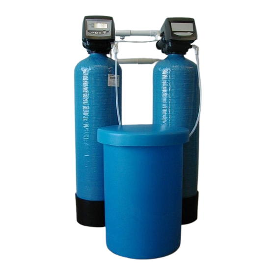
- Page 1 Duplex Commercial Softeners Installation, Operation & Maintenance Guide Manual 003.1...
-
Page 2: Table Of Contents
Contents Page Unpacking Instructions Installation Pre-installation checks Fitting the bottom distribution systems Adding the media Fitting the valves Brine tank connections Hydraulic connections Drain line flow connections Electrical Connections Programming the valves Resetting the valve programming In Service Display Commissioning Introduction Regeneration Service... -
Page 3: Unpacking Instructions
Thank you for purchasing this Softener. We are sure that it will provide you with trouble free service for many years to come. Please use the following pages to assist you with the assembly and installation of your new system. 1. -
Page 4: Installation
2. Installation. Please observe the regulations concerning the installation of your water softener. Check that you have allowed space for access to the unit for possible future maintenance. This installation may require plumbing work and will require an electrical outlet to be fitted near the system. -
Page 5: Brine Tank Connections
¾” or 1” valves; these can be connected using fixed or flexible pipe work. Duplex systems with 2” valves do not come with interconnecting pipe work kits and will need to be plumbed on site with connections to the 2” solvent weld tails provided. -
Page 6: Electrical Connections
Fig A.12 2.9 Programming the Valve set. This programming relates to the Autotrol 764 logix duplex valve sets. The valve set should already have been set up with the basic settings in the factory. The only settings you should need to enter are the time of day and day of the week. All settings are set on the master controller. - Page 7 By repeatedly pressing the set button you can scroll to the part of the set up programme you require. You may receive an ERR3 / ERR4 message, if this happens allow the cam shafts to turn for a few moments and this code should disappear. If the cam does not move check that the Cam Shafts are fitted correctly and that the optical sensors are in position.
-
Page 8: Resetting The Valve Programming
2.10 Resetting the Valve Programming. Occasionally it maybe necessary to reset the valve to factory defaults. The programmed valve type (softener) can be checked by pressing and holding the SET and DOWN buttons simultaneously for 5 seconds. H0 and a resin volume is displayed e.g. H0 100, the valve has been set as a softener. -
Page 9: Service
continue through the regeneration cycle, this will allow you to check for leaks and also purge any remaining air from the system. After a backwash the system will move through a brine draw routine, some pressure equalising and further rinse cycles before stopping in the service position. - Page 10 5.2 Programming Details and Operating Data. Small Commercial Softeners Vessel Size 1035 1044 1054 1248 1354 Media Volume (each vessel) Valve Type Parameters Time of day (HH:MM) Set on site Day of week Set on site Time of regeneration (HH:MM) P3 Set on site / factory default 2,00am Calendar overide days Set on site / factory default 14 days...
- Page 11 5.3 Typical Installation layout. Drain elbow Valve Upper screen Brine line Riser Drain line Brine tank Containing Brine pickups Overflow Lower Screen Salt Base Typical bypass setup using Isolation Valve three isolation valves plus Softener Outlet a non return valve. Bypass Valve Isolation Valve Softener Inlet...
- Page 12 5.4 Troubleshooting. Following you can find a guide as to the most common problems that may arise; please consult this section before contacting you supplying dealer as most problems are easily cured by following this information. 700 Series Controller Troubleshooting. Problem Possible cause Solution...
- Page 13 System Troubleshooting Problem Possible cause Solution 1. Regenerant Tank Overflow. a. Drain line restricted. a. Check the drain line is not blocked or kinked. See also 4. b. Uncontrolled refill flow rate b. Remove refill flow control to clean ball and seat. c.
- Page 14 System Troubleshooting Problem Possible cause Solution 9. Valve will not draw brine. a. Low water pressure a. Fit pump (contact dealer) b. Drain line restriced. b. Check the drain line is not blocked or kinked. c. Injector plugged. c. Clean injector and screen. d.
- Page 15 Notes:...
- Page 16 Manual 003.1...
Need help?
Do you have a question about the Duplex and is the answer not in the manual?
Questions and answers