Table of Contents
Advertisement
QM_XC7A35T_SDRAM CORE BOARD
USER MANUAL
Preface
The QMTech® XC7A35T SDRAM core board uses Xilinx Artix®-7 devices to demonstrate the highest
performance-per-watt fabric, transceiver line rates, DSP processing, and AMS integration in a cost-
MicroBlaze™ soft processor
optimized FPGA. Featuring the
and 1,066Mb/s DDR3 support, the family is the
best value for a variety of cost and power-sensitive applications including software-defined radio, machine
vision cameras, and low-end wireless backhaul.
QM_XC7A35T_SDRAM Core Board
User Manual V02
Advertisement
Table of Contents

Related Manuals for QMTECH XC7A35T SDRAM


Summary of Contents for QMTECH XC7A35T SDRAM
- Page 1 QM_XC7A35T_SDRAM CORE BOARD USER MANUAL Preface The QMTech® XC7A35T SDRAM core board uses Xilinx Artix®-7 devices to demonstrate the highest performance-per-watt fabric, transceiver line rates, DSP processing, and AMS integration in a cost- MicroBlaze™ soft processor optimized FPGA. Featuring the...
-
Page 2: Table Of Contents
Table of Contents INTRODUCTION .................. 3 ..............3 OCUMENT COPE ................3 VERVIEW GETTING STARTED ................4 ............5 NSTALL EVELOPMENT OOLS QM_XC7A35T_SDRAM H ........ 6 ARDWARE ESIGN 2.2.1 QM_XC7A35T_SDRAM Power Supply ......6 2.2.2 QM_XC7A35T_SDRAM SPI Boot ......... 7 2.2.3 QM_XC7A35T_SDRAM Memory ......... -
Page 3: Introduction
Introduction Document Scope This demo user manual introduces the QM_XC7A35T_SDRAM core board and describes how to setup the core board running with application software Xilinx Vivado 2016.4. Users may employee the on board rich logic resource FPGA XC7A35T-1FTG256C and large SDRAM memory MT48LC16M16 to implement various applications. -
Page 4: Getting Started
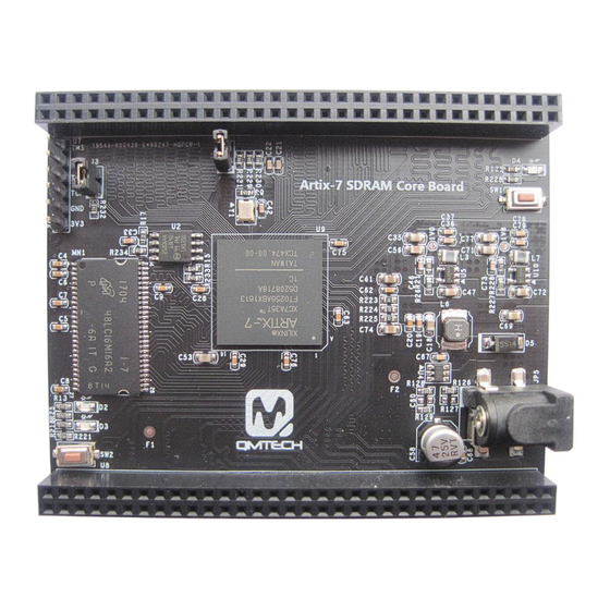
Getting Started The QM_XCA35T_SDRAM core board includes below item: Figure 2-1. QM_XC7A35T_SDRAM Top View Below image shows the dimension of the QM_XC7A35T_SDRAM core board: 6.7cm x 8.4cm. The unit in below image is millimeter(mm). Figure 2-2. QM_XC7A35T_SDRAM Core Board Dimension QM_XC7A35T_SDRAM Core Board User Manual V02... -
Page 5: Install Development Tools
Install Development Tools The QM_XC7A35T_SDRAM core board tool chain consists of Xilinx Vivado 2016.4, Xilinx USB platform cable, XC7A35T core board and 5V DC power supply. Below image shows the Xilinx Vivado 2016.4 development environment which could be downloaded from Xilinx office website: Figure 2-3. -
Page 6: Qm_Xc7A35T_Sdram Hardware Design
QM_XC7A35T_SDRAM Hardware Design 2.2.1 QM_XC7A35T_SDRAM Power Supply The core board needs 5V DC input as power supply which could be directly injected from power header or the 64P female header U7/U8. Users may refer to the hardware schematic for the detailed design. The on board LED D4 indicates the 3.3V supply, it will be turned on when the 5V power supply is active. -
Page 7: Qm_Xc7A35T_Sdram Spi Boot
2.2.2 QM_XC7A35T_SDRAM SPI Boot In default, QM_XC7A35T boots from external SPI Flash, detailed hardware design is shown in below figure. The SPI flash is using N25Q064 manufactured by Micron, with 64Mbit memory storage. FPGA_CSO_B 4.7K FPGA_DQ1 FPGA_DQ3 4.7K R234 SO/SIO1 SIO3 FPGA_DQ2 FPGA_CCLK... -
Page 8: Qm_Xc7A35T_Sdram Memory
2.2.3 QM_XC7A35T_SDRAM Memory QM_XC7A35T has on board 16bit width data bus, 32MB memory size SDRAM MT48LC16M16 provided by Micron. Below image shows the detailed hardware design: MT48LC16M16A2 DQ10 DQ11 DQ12 DQ13 DQ14 DQ15 SDCKE0 VDDQ SDCLK0 VDDQ VDDQ DQML DQML VDDQ DQMH DQMH... -
Page 9: Qm_Xc7A35T_Sdram Extension Io
2.2.5 QM_XC7A35T_SDRAM Extension IO The core board has two 64P 2.54mm pitch female headers which are used for extending user modules, such as ADC/DAC module, audio/video module, ethernet module, etc. VCCO_34_35 VCCO_34_35 BANK34/35 Voltage BANK35_B7 BANK35_A7 Supply Pins. BANK35_B6 BANK35_B5 BANK35_E6 BANK35_K5 BANK35_J5... -
Page 10: Qm_Xc7A35T_Sdram 3.3V Power Supply
2.2.1 QM_XC7A35T_SDRAM 3.3V Power Supply The core board’s 3.3V power supply is using high efficiency DC/DC chip MP2359 provided by MPS Inc. The MP2359 supports wide voltage input range from 4.5V to 24V. In normal use case, 5V DC power supply is suggested to be applied on the board. -
Page 11: Qm_Xc7A35T_Sdram User Key
2.2.4 QM_XC7A35T_SDRAM User Key Below image shows the PROGRAM_B key and one user key: R228 R221 4.7k 4.7k PROG_B BANK15_A8 Figure 2-15. Keys QM_XC7A35T_SDRAM Core Board User Manual V02... -
Page 12: Reference
Reference [1] ug470_7Series_Config.pdf [2] ds181_Artix_7_Data_Sheet.pdf [3] ug475_7Series_Pkg_Pinout.pdf [4] n25q_64a_3v_65nm.pdf [5] MT48LC16M16.pdf [6] MP2359.pdf [7] NCP1529-D.PDF QM_XC7A35T_SDRAM Core Board User Manual V02... -
Page 13: Revision
Revision Doc. Rev. Date Comments 05/10/2017 Initial Version. 05/14/2017 V1.0 Formal Release. 18/02/2018 Update PCB color to black. QM_XC7A35T_SDRAM Core Board User Manual V02...
Need help?
Do you have a question about the XC7A35T SDRAM and is the answer not in the manual?
Questions and answers