Table of Contents
Advertisement
XILINX SPARTAN-7 CORE BOARD
USER MANUAL
Preface
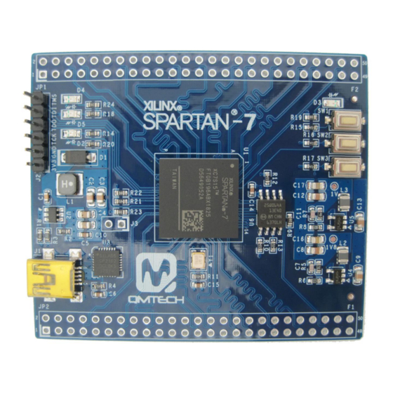
The QMTech® Spartan-7 Core Board uses Xilinx XC7S15 device to demonstrate the newest
addition to the Cost-Optimized Portfolio, offer the best in class performance per watt, along
with small form factor packaging to meet the most stringent requirements. These devices
feature a MicroBlaze™ soft processor running over 200 DMIPs with 800Mb/s DDR3 support
built on 28nm technology. Additionally, Spartan-7 devices offer an integrated ADC, dedicated
security features, and Q-grade (-40 to +125° C) on all commercial devices. These devices are
ideally suited for industrial, consumer, and automotive applications including any-to-any
connectivity, sensor fusion, and embedded vision.
QM_Spartan-7 Development Board
User Manual V01
Advertisement
Table of Contents

Subscribe to Our Youtube Channel
Related Manuals for QMTECH XILINX SPARTAN-7


Summary of Contents for QMTECH XILINX SPARTAN-7
- Page 1 USER MANUAL Preface The QMTech® Spartan-7 Core Board uses Xilinx XC7S15 device to demonstrate the newest addition to the Cost-Optimized Portfolio, offer the best in class performance per watt, along with small form factor packaging to meet the most stringent requirements. These devices feature a MicroBlaze™...
-
Page 2: Table Of Contents
Table of Contents INTRODUCTION .................. 3 ..............3 OCUMENT COPE ................3 VERVIEW GETTING STARTED ................4 ............4 NSTALL EVELOPMENT OOLS QM_S -7 H ..........7 PARTAN ARDWARE ESIGN 2.2.1 QM_Spartan-7 Power Supply ........7 2.2.1 QM_Spartan-7 3.3V Power Supply ......8 2.2.2 QM_Spartan-7 SPI Boot .......... -
Page 3: Introduction
Introduction Document Scope This demo user manual introduces the QM_Spartan-7 development board and describes how to setup the development board running with application software Xilinx Vivado 2018.2. Users may employee the on board rich logic resource FPGA XC7S15-1FTGB196C to implement various applications. The development board has 88 non-multiplexed FPGA IOs for extending customized modules, such as UART module, CMOS/CCD camera module, LCD/HDMI/VGA display module etc. -
Page 4: Getting Started
Getting Started Below image shows the dimension of the QM_Spartan-7 development board: 6.6cm x 5.7cm. The unit in below image is millimeter(mm). Figure 2-1. QM_Spartan-7 Development Board Dimension Install Development Tools The QM_Spartan-7 development board tool chain consists of Xilinx Vivado 2018.2, Xilinx USB platform cable, Mini USB cable for power supply. - Page 5 Below image shows the JTAG connection between Xilinx USB platform cable and QM_Spartan-7 development board: (Green) (Purple) (White) TCK (Yellow) (Black) VREF (Red) 5V DC Figure 2-3. JTAG Connection and Power Supply Once the FPGA test program is correctly 【Synthesized】, 【Implemented】 and 【Generated with Bitstream】, users may click the 【Open Target】...
- Page 6 Chip info like xc7s15_0(1) is shown in Hardware Manager as below image. Users then could right click the device to choose 【Program Device】to load the Bitstream *.bit into FPGA or to choose【Add Configuration Memory Device】to program the *.mcs file into on-board SPI flash. Figure 2-5.
-
Page 7: Qm_Spartan-7 Hardware Design
QM_Spartan-7 Hardware Design 2.2.1 QM_Spartan-7 Power Supply The development board needs 5V DC input as power supply which could be directly injected from JP1/JP2 header or the Mini USB connector. Users may refer to the hardware schematic for the detailed design. The on board LED D5 indicates the 3.3V supply, it will be turned on when the 5V power supply is active. -
Page 8: Qm_Spartan-7 3.3V Power Supply
2.2.1 QM_Spartan-7 3.3V Power Supply The development board’s 3.3V power supply is using high efficiency DC/DC chip MP2359 provided by MPS Inc. The MP2359 supports wide voltage input range from 4.5V to 24V. In normal use case, 5V DC power supply is suggested to be applied on the board. -
Page 9: Qm_Spartan-7 Spi Boot
Figure 2-10. 1.8V AUX Voltage DC/DC 2.2.2 QM_Spartan-7 SPI Boot In default, XC7S15 boots from external SPI Flash, detailed hardware design is shown in below figure. The SPI flash is using N25Q064 manufactured by Micron, with 64Mbit memory storage. FPGA_CSO_B 4.7K FPGA_DQ1 FPGA_DQ3... -
Page 10: Qm_Spartan-7 System Clock
Figure 2-13. FPGA_DONE Status Indicator 2.2.3 QM_Spartan-7 System Clock FPGA chip XC7S15-1FTGB196C has system clock frequency 50MHz which is directly provided by external crystal. The crystal is designed with high accuracy and stability with low temperature drift 10ppm/°c. Below image shows the detailed hardware design: 50 MHz Figure 2-14. -
Page 11: Qm_Spartan-7 Extension Io
LED_D4 LED_D3 Figure 2-16. LEDs 2.2.6 QM_Spartan-7 Extension IO The development board has two 50P 2.54mm pitch headers which are used for extending user modules, such as ADC/DAC module, audio/video module, ethernet module, etc. QM_Spartan-7 Development Board User Manual V01... -
Page 12: Qm_Spartan-7 User Key
USB_5V IO_P4 IO_P3 IO_P2 IO_N1 IO_M5 IO_M4 IO_M3 IO_M2 IO_M1 IO_L1 IO_L3 IO_L2 IO_K4 IO_K3 IO_J4 IO_J3 IO_J2 IO_J1 IO_H3 IO_H4 IO_H1 IO_H2 IO_F4 IO_G4 IO_F3 IO_F2 IO_F1 IO_G1 IO_C1 IO_D1 IO_D2 IO_E2 IO_B2 IO_B1 IO_D4 IO_E4 IO_B3 IO_A2 IO_A4 IO_A3 IO_C3 IO_D3... -
Page 13: Qm_Spartan-7 Uart Port
4.7k 4.7k 4.7K PROG_B KEY 0 nRESET Figure 2-18. Keys 2.2.8 QM_Spartan-7 UART Port The CP2102-GMR is a USB 2.0 to serial port bridge chip designed by Silicon Labs. The CP2102-GMR includes a USB 2.0 full-speed function controller, USB transceiver, oscillator, UART and eliminates the need for other external USB components are required for development. -
Page 14: Reference
Reference [1] ug470_7Series_Config.pdf [2] ds181_Artix_7_Data_Sheet.pdf [3] ug475_7Series_Pkg_Pinout.pdf [4] n25q_64a_3v_65nm.pdf [5] MP2359.pdf [6] NCP1529-D.PDF QM_Spartan-7 Development Board User Manual V01... -
Page 15: Revision
Revision Doc. Rev. Date Comments 05/12/2018 Initial Version. 05/12/2018 V1.0 Formal Release. QM_Spartan-7 Development Board User Manual V01...
Need help?
Do you have a question about the XILINX SPARTAN-7 and is the answer not in the manual?
Questions and answers