
Related Manuals for NSC Sicherheitstechnik Solution F2

Summary of Contents for NSC Sicherheitstechnik Solution F2
- Page 1 Fire Control Panels “Solution F2” Operating and Installation Manual Issue: May 2011 NSC Sicherheitstechnik GmbH 1/47 2011 / 04 / 26 Eckendorfer Str. 125 c Installation Manual Solution F2 20110509.doc 33609 Bielefeld Version S031A01.01...
- Page 2 NSC Sicherheitstechnik GmbH 2/47 2011 / 04 / 26 Eckendorfer Str. 125 c Installation Manual Solution F2 20110509.doc 33609 Bielefeld Version S031A01.01...
-
Page 3: Table Of Contents
Manual Control: 4 monitored Power Outputs ................26 Manual Control: Output modules (loop) ................... 26 Menu „Simulation“ ........................26 Menu „Revision“ ........................27 NSC Sicherheitstechnik GmbH 3/47 2011 / 04 / 26 Eckendorfer Str. 125 c Installation Manual Solution F2 20110509.doc 33609 Bielefeld Version S031A01.01... - Page 4 ESPA 4.4.4 Settings ......................... 33 Modbus Einstellungen ......................33 Firmware Update ........................... 34 For the flash update of the Solution F2 firmware you need the following items:...... 34 Preparation ..........................34 Start of Bootloader & Flash Update Routine ................34 Execute flash update ........................
-
Page 5: Description Of Control Panel
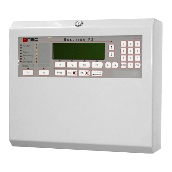
1. Description of Control Panel: Picture of the control panel of the "Solution F2": LED indications Dynamic functions keys F1 – F4, Keypad and cursor push buttons The functions are individually indicated in the bottom line of the LC module Field programmable push buttons S1 –... -
Page 6: Lc Module Indications
F1 – F4. Sometimes all 4 keys are used, sometimes only NSC Sicherheitstechnik GmbH 6/47 2011 / 04 / 26 Eckendorfer Str. 125 c Installation Manual Solution F2 20110509.doc 33609 Bielefeld Version S031A01.01... -
Page 7: Description Of The Push Buttons
Use this push button in the menus to cancel your inputs. Cursor control keypad. Configuration: The configuration of the fire control panel "Solution F2" has to be done generally by the PC configuration software. With Firmware release 1.00 and following the data communication between panel amd pc must be enabled by user- or installercode. - Page 8 You have to type in the installer code to get access to the relating menus (s. menu 20) NSC Sicherheitstechnik GmbH 8/47 2011 / 04 / 26 Eckendorfer Str. 125 c Installation Manual Solution F2 20110509.doc 33609 Bielefeld Version S031A01.01...
-
Page 9: Menus For The End User
The fire protection outputs CAN NOT be switched off during alarm state. Jump to Menu 02.9 NSC Sicherheitstechnik GmbH 9/47 2011 / 04 / 26 Eckendorfer Str. 125 c Installation Manual Solution F2 20110509.doc 33609 Bielefeld Version S031A01.01... -
Page 10: Switching On/Off: Zones And Single Detectors
Switch on/off from output : 001 normal Here the 8 OC-outputs on the main processor board to output of the FCP "Solution F2” as well as the 9 OC-outputs ↓+1 ↑-1 Selection -> +10 <- -10 on the F2 io extension can be switched on/off. -
Page 11: Switching On/Off: 6 Internal Relays
„on/off like sounders“. By the function (F3) all sounders and strobes will be switched off continuously. If another alarm NSC Sicherheitstechnik GmbH 11/47 2011 / 04 / 26 Eckendorfer Str. 125 c Installation Manual Solution F2 20110509.doc 33609 Bielefeld Version S031A01.01... -
Page 12: Switching On/Off: Alarm Transmission Device (Td)
02.8 Switching on/off: Alarm transmission delay Switch on/off Here the delay of the alarm transmission device of the 1. Zones & detect. 5. Sounder/Strobe FCP „Solution F2” can be switched on/off. 2. Output 6. Alarm Trans.Dev. 3. Relay 7. Delay After selecting this function you see at the bottom line 4. -
Page 13: Changing The End User Access Code
06.1 By pressing F3 („print“) Jump to Menu 06.2 06.1 Event memory: "Filter“ Filter The FCP Solution F2 saves all messages in its event 1. Alarm x 5. Off memory. 2. Pre alarm x 6. Activation 3. Test alarm This filter functions allows displaying only certain kind 4. -
Page 14: Event Memory: "Printing
Pressing F2 again will show all configured detectors again. One detector is shown per line. The grey line have the following meanings : NSC Sicherheitstechnik GmbH 14/47 2011 / 04 / 26 Eckendorfer Str. 125 c Installation Manual Solution F2 20110509.doc 33609 Bielefeld Version S031A01.01... - Page 15 Ion. Det. XP95 Ionisation smoke detect. Heat det. XP95 Heat detector H.Thermo. XP95 Heat detector high temperatur Multisen. XP95 Multisensor NSC Sicherheitstechnik GmbH 15/47 2011 / 04 / 26 Eckendorfer Str. 125 c Installation Manual Solution F2 20110509.doc 33609 Bielefeld Version S031A01.01...
-
Page 16: Example Of Detector Data: Mcp
The last but one line shows any additional fault information if the detector/module is not in normal condition (here: fault because detector is missing). NSC Sicherheitstechnik GmbH 16/47 2011 / 04 / 26 Eckendorfer Str. 125 c Installation Manual Solution F2 20110509.doc 33609 Bielefeld Version S031A01.01... -
Page 17: Example Of Detector Data: Optical Smoke Detector
Example of „Zeropoint“ and „Firepoint“ display ______|______ ______|_____ Zeropoint = quiescent analogue value Zeropoint Firepoint (9-109 depending on detector type) NSC Sicherheitstechnik GmbH 17/47 2011 / 04 / 26 Eckendorfer Str. 125 c Installation Manual Solution F2 20110509.doc 33609 Bielefeld Version S031A01.01... -
Page 18: Only For Apollo Discovery
1 = LED flashes, if detector is polled. • 0 = LED off, if detector is polled this function can be set by system-parameter 8 NSC Sicherheitstechnik GmbH 18/47 2011 / 04 / 26 Eckendorfer Str. 125 c Installation Manual Solution F2 20110509.doc 33609 Bielefeld Version S031A01.01... -
Page 19: Hardware Modules: Overview
"ccAll accept after restart" is activated. Possible messages are: • Call acceptance on • Call acceptance off • RING (of other modem) NSC Sicherheitstechnik GmbH 19/47 2011 / 04 / 26 Eckendorfer Str. 125 c Installation Manual Solution F2 20110509.doc 33609 Bielefeld Version S031A01.01... -
Page 20: Display Of Frp/Lcd Panel
3 and an short circuit for line 4. cancel Leaving the menu by pressing F1 („Cancel“). NSC Sicherheitstechnik GmbH 20/47 2011 / 04 / 26 Eckendorfer Str. 125 c Installation Manual Solution F2 20110509.doc 33609 Bielefeld Version S031A01.01... -
Page 21: Example Of Input Voltages
FCP data Serial No. Software version S031A01.00 SL031A00.11 Leaving the menu by pressing F1 („Cancel“). Serial number 1711/0067 Cancel NSC Sicherheitstechnik GmbH 21/47 2011 / 04 / 26 Eckendorfer Str. 125 c Installation Manual Solution F2 20110509.doc 33609 Bielefeld Version S031A01.01... -
Page 22: Menus For The Installer
Usually the bottom line of the LC module looks like this (if there are no additional options to F2 and F3): Cancel Enter NSC Sicherheitstechnik GmbH 22/47 2011 / 04 / 26 Eckendorfer Str. 125 c Installation Manual Solution F2 20110509.doc 33609 Bielefeld Version S031A01.01... -
Page 23: Access To The Installer Menu
Instead you can also select the function by pressing the no. left in front of the functions (here: 1 – 8). NSC Sicherheitstechnik GmbH 23/47 2011 / 04 / 26 Eckendorfer Str. 125 c Installation Manual Solution F2 20110509.doc 33609 Bielefeld Version S031A01.01... -
Page 24: Main Menu: Test Functions
Evt. individual detector text detector goes into alarm condition. ██████████████████████ A-Value 4,5%/m Pre alarm███████████████ 2,7%/m █████████████████ Alarm 3,4%/m Cancel Calib. Details NSC Sicherheitstechnik GmbH 24/47 2011 / 04 / 26 Eckendorfer Str. 125 c Installation Manual Solution F2 20110509.doc 33609 Bielefeld Version S031A01.01... -
Page 25: Menu "Manual Controlling
003 Relay 003 Main board Cancel Enter The way of operation is the same as in Menu 24. NSC Sicherheitstechnik GmbH 25/47 2011 / 04 / 26 Eckendorfer Str. 125 c Installation Manual Solution F2 20110509.doc 33609 Bielefeld Version S031A01.01... -
Page 26: Manual Control: 4 Monitored Power Outputs
LC module displays „ALARM“ The alarm has to be reset by Reset FCP Press cancel (F1) to leave this menu. NSC Sicherheitstechnik GmbH 26/47 2011 / 04 / 26 Eckendorfer Str. 125 c Installation Manual Solution F2 20110509.doc 33609 Bielefeld Version S031A01.01... -
Page 27: Menu „Revision
Please type the right data line by line and confirm Month : 07 Winter every line by OK. NSC Sicherheitstechnik GmbH 27/47 2011 / 04 / 26 Eckendorfer Str. 125 c Installation Manual Solution F2 20110509.doc 33609 Bielefeld Version S031A01.01... -
Page 28: Maintenance
& impulse feedback FCP cover Deactivated contact Switch off TD Switch on and off Mains fault delay 0-30 Minutes NSC Sicherheitstechnik GmbH 28/47 2011 / 04 / 26 Eckendorfer Str. 125 c Installation Manual Solution F2 20110509.doc 33609 Bielefeld Version S031A01.01... -
Page 29: Scanning Rs485 Devices
RSRS485 Devices : 001 ------------------ Scan detectors Scan detectors Loop module : This menu relates to addressable detectors only. NSC Sicherheitstechnik GmbH 29/47 2011 / 04 / 26 Eckendorfer Str. 125 c Installation Manual Solution F2 20110509.doc 33609 Bielefeld Version S031A01.01... -
Page 30: Delete Configuration
Opens input screen to adjust the power outputs jump to Menü Opens input screen to configure the loops jump to Menu NSC Sicherheitstechnik GmbH 30/47 2011 / 04 / 26 Eckendorfer Str. 125 c Installation Manual Solution F2 20110509.doc 33609 Bielefeld Version S031A01.01... -
Page 31: Changing The Installer Access Code
On (F2). The activation will be indicated in Cancel save the 1 display line. By pressing Off (F3) the protocol will be deactivated again. NSC Sicherheitstechnik GmbH 31/47 2011 / 04 / 26 Eckendorfer Str. 125 c Installation Manual Solution F2 20110509.doc 33609 Bielefeld Version S031A01.01... -
Page 32: Modem Functions
NSC Sicherheitstechnik GmbH 32/47 2011 / 04 / 26 Eckendorfer Str. 125 c Installation Manual Solution F2 20110509.doc 33609 Bielefeld Version S031A01.01... -
Page 33: Options
Hier kann die Slave Adresse für das Modbus Slave address : 001 PLC Protokoll festgelegt werden. Cancel save NSC Sicherheitstechnik GmbH 33/47 2011 / 04 / 26 Eckendorfer Str. 125 c Installation Manual Solution F2 20110509.doc 33609 Bielefeld Version S031A01.01... -
Page 34: Firmware Update
If no input will be done within 30 seconds the actual firmware will start automatically. The same result you get by pressing key '1'. By pressing key '2' the flash update routine of the Solution F2 will be started and the actual flash status will be displayed. -
Page 35: Execute Flash Update
"file open" dialog you then have to select the new firmware file (file extension xmot). In the upper area of the window the status of the Solution F2 will be displayed. On the left side the actual firmware versions of the panel will be displayed, on the right side you can see the new versions.from the firmware file. -
Page 36: Errors And Possible Reasons
After the updates have finished you can leave the program by pressing the "Ende / Exit" button. At the panel Solution F2 you can leave the flash update routine by pressing the "ESC" key. Then you reach again the bootloader menu and you can start the firmware by pressing '1'. After a short time there should bet the initialization display present followed by the display of recognized hardware modules. - Page 37 PC and and success message has not been received. Remedy: deactivate the erase function and program again that microcontroller. If the flash memory is marked as "not empty" also at the Solution F2, the command hasn't been executed correctly.
-
Page 38: Mounting Instruction
1. First please remove the cover of the FCP. You will find the key on the backside of the panel housing. 2. In the FCP Solution F2 package you will find a drilling template for easier mounting. Please use this template for drilling the holes. -
Page 39: Commissioning Of Solution F2
6. Commissioning of Solution F2 ____________________________________________ ____________________________________________ Serial number Date of delivery ____________________________________________ ____________________________________________ Commission/ Sight Installed by : date, technician General The commissioning according the national rules requires the complete and accurate installation of all components of fire control system, as it is specified in the engineering documents. -
Page 40: Measure Cable Resistance Of Loop Wiring (Without Voltage)
Ο fault I/O extension tolerance 10% Ο ok Extinguish interface 3,3KΩ/0,5W Ο fault main board tolerance 10% Ο ok NSC Sicherheitstechnik GmbH 40/47 2011 / 04 / 26 Eckendorfer Str. 125 c Installation Manual Solution F2 20110509.doc 33609 Bielefeld Version S031A01.01... -
Page 41: Checking The End Of Line Resistor On The Rs485 Bus
By pressing the "Details“ key F3 the addresses of the modules can be checked. Exampel: Hardware modules 01/02 >01 Detector module HOCHIKI ESP 02 Detector module HOCHIKI ESP Cancel Details NSC Sicherheitstechnik GmbH 41/47 2011 / 04 / 26 Eckendorfer Str. 125 c Installation Manual Solution F2 20110509.doc 33609 Bielefeld Version S031A01.01... -
Page 42: Serial Devices
- Segment (loop), where the device is connected to - Symbol for loop "o" or spur wiring "-" - number of loop/spur NSC Sicherheitstechnik GmbH 42/47 2011 / 04 / 26 Eckendorfer Str. 125 c Installation Manual Solution F2 20110509.doc 33609 Bielefeld Version S031A01.01... -
Page 43: Checking Of Earth Fault
F3. The software then calculates the thresholds for open curcuit and short curcuit. The resistance can also be measured with a multimeter and typed in directly using the keyboard. NSC Sicherheitstechnik GmbH 43/47 2011 / 04 / 26 Eckendorfer Str. 125 c Installation Manual Solution F2 20110509.doc 33609 Bielefeld Version S031A01.01... -
Page 44: Configuration Of The Fire Control System
Ο not used Interfaces Configuration -> more Ο ok Ο not used Thresholds for conventional zones Configuration -> more NSC Sicherheitstechnik GmbH 44/47 2011 / 04 / 26 Eckendorfer Str. 125 c Installation Manual Solution F2 20110509.doc 33609 Bielefeld Version S031A01.01... -
Page 45: Functional Tests
Current of FCP at mains fault ....mA Required bridge over time ………….h Required battery capacity Ο ok. Ο fault …………Ah NSC Sicherheitstechnik GmbH 45/47 2011 / 04 / 26 Eckendorfer Str. 125 c Installation Manual Solution F2 20110509.doc 33609 Bielefeld Version S031A01.01... -
Page 46: Technical Specifications
230V AC, -15% bis +10%, 50 – 60 Hz Operating voltage : 24V DC (21,0 – 29,2 V DC) Output supply current Solution F2 (Art. B01070-00) : Max. 2,5 A Battery charging current Solution F2 (Art. B01070-00) : Max. 1,3 A Output supply current Solution F2 (Art. -
Page 47: Ce Marking
Test condition (EN54-2, Cl. 10) Standardized I/O interface (EN54-2, Cl. 11) For technical data see chapter 7 of this manual. NSC Sicherheitstechnik GmbH 47/47 2011 / 04 / 26 Eckendorfer Str. 125 c Installation Manual Solution F2 20110509.doc 33609 Bielefeld Version S031A01.01...
Need help?
Do you have a question about the Solution F2 and is the answer not in the manual?
Questions and answers