Yamaha BD-S677 Service Manual
Hide thumbs
Also See for BD-S677:
- Owner's manual (67 pages) ,
- Owner's manual (109 pages) ,
- Owner's manual (344 pages)
Table of Contents
Advertisement
* When the MAIN P.C.B. or Wi-Fi module is replaced, the serial number, new MAC (Wired) address and new
MAC (Wireless) address MUST be reported to Yamaha Corporation by e-mail.
For more information, refer to "SERVICE PRECAUTIONS".
This manual has been provided for the use of authorized Yamaha Retailers and their service personnel.
It has been assumed that basic service procedures inherent to the industry, and more specifi cally Yamaha Products, are already known
and understood by the users, and have therefore not been restated.
WARNING:
IMPORTANT:
The data provided is believed to be accurate and applicable to the unit(s) indicated on the cover. The research, engineering, and service
departments of Yamaha are continually striving to improve Yamaha products. Modifi cations are, therefore, inevitable and specifi cations
are subject to change without notice or obligation to retrofi t. Should any discrepancy appear to exist, please contact the distributor's
Service Division.
WARNING:
IMPORTANT:
■ CONTENTS
TO SERVICE PERSONNEL ........................................2-4
REGION MANAGEMENT INFORMATION .....................6
FRONT PANEL ...............................................................7
REAR PANELS ...........................................................7-9
REMOTE CONTROL PANELS ..................................... 10
SPECIFICATIONS ................................................... 11-12
INTERNAL VIEW .......................................................... 13
SERVICE PRECAUTIONS ...................................... 14-16
DISASSEMBLY PROCEDURES ............................. 17-18
1 0 1 2 9 8
BLU-RAY DISC PLAYER
BD-S677
E-mail: ycav-keycontrol@gmx.yamaha.com
IMPORTANT NOTICE
Failure to follow appropriate service and safety procedures when servicing this product may result in personal injury,
destruction of expensive components, and failure of the product to perform as specifi ed. For these reasons, we advise
all Yamaha product owners that any service required should be performed by an authorized Yamaha Retailer or the
appointed service representative.
The presentation or sale of this manual to any individual or fi rm does not constitute authorization, certifi cation or
recognition of any applicable technical capabilities, or establish a principle-agent relationship of any form.
Static discharges can destroy expensive components. Discharge any static electricity your body may have
accumulated by grounding yourself to the ground buss in the unit (heavy gauge black wires connect to this buss).
Turn the unit OFF during disassembly and part replacement. Recheck all work before you apply power to the unit.
Copyright (c) Yamaha Corporation All rights reserved.
This manual is copyrighted by Yamaha and may not be copied or
redistributed either in print or electronically without permission.
SERVICE MANUAL
REWRITING OPU PARAMETER ............................ 19-25
FRONT PANEL KEYS LOCK MODE ............................26
BLOCK DIAGRAM ........................................................27
WIRING DIAGRAM .......................................................28
PRINTED CIRCUIT BOARDS .................................29-30
SCHEMATIC DIAGRAMS .......................................31-42
REPLACEMENT PARTS LIST ................................44-45
REMOTE CONTROL ...............................................46-47
SETUP MENU ...............................................................48
SOFTWARE UPGRADE ...............................................49
P.O.Box 1, Hamamatsu, Japan
'14.04
Advertisement
Table of Contents

Related Manuals for Yamaha BD-S677


Summary of Contents for Yamaha BD-S677
-
Page 1: Table Of Contents
This manual has been provided for the use of authorized Yamaha Retailers and their service personnel. It has been assumed that basic service procedures inherent to the industry, and more specifi cally Yamaha Products, are already known and understood by the users, and have therefore not been restated. -
Page 2: To Service Personnel
BD-S677 ■ TO SERVICE PERSONNEL AC LEAKAGE 1. Critical Components Information WALL EQUIPMENT TESTER OR OUTLET UNDER TEST EQUIVALENT Components having special characteristics are marked ⚠ and must be replaced with parts having specifications equal to those originally installed. 2. Leakage Current Measurement (For 120V Models Only) - Page 3 BD-S677 WARNING: Laser Safety This product contains a laser beam component. This component may emit invisible, as well as visible radiation, which may cause eye damage. To protect your eyes and skin from laser radiation, the following precautions must be used during servicing of the unit.
- Page 4 BD-S677 CAUTION Use of controls or adjustments or performance of CAUTION: INVISIBLE LASER RADIATION WHEN OPEN. procedures other than those specified herein may result DO NOT STARE INTO BEAM. in hazardous radiation exposure. DANGER: INVISIBLE LASER RADIATION WHEN OPEN. AVERTISSEMENT AVOID DIRECT EXPOSURE TO THE BEAM.
-
Page 5: Prevention Of Electrostatic Discharge
BD-S677 ■ PREVENTION OF ELECTROSTATIC DISCHARGE Some semiconductor (solid state) devices can be damaged easily by static electricity. Such components commonly are called Electrostatically Sensitive (ES) Devices. Examples of typical ES devices are integrated circuits and some field-effect transistors and semiconductor “chip” components. The following techniques should be used to help reduce the incidence of component damage caused by electrostatic discharge (ESD). -
Page 6: Region Management Information
BD-S677 ■ REGION MANAGEMENT INFORMATION This BD/DVD player is designed and manufactured to respond to the Region Management Information that is recorded on a BD/DVD disc. If the Region code/number described on the BD/DVD disc does not correspond to the Region code/ number of this BD/DVD player, this BD/DVD player cannot play this disc. -
Page 7: Front Panel
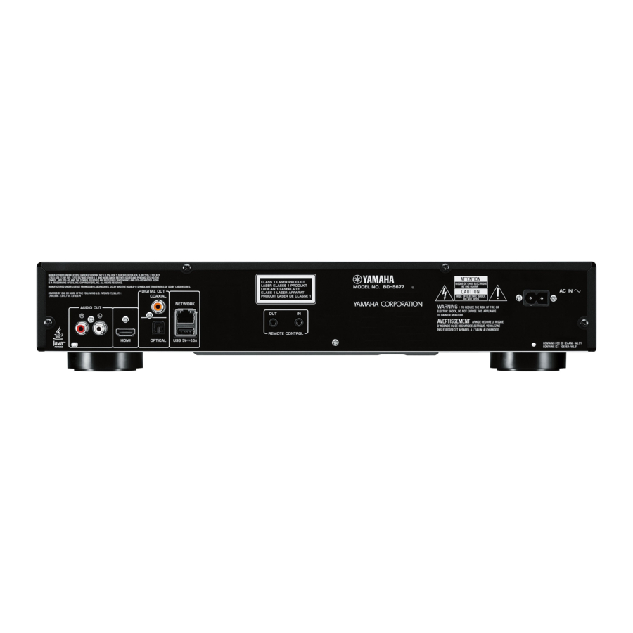
BD-S677 ■ FRONT PANEL ■ REAR PANELS U model C model T model... - Page 8 BD-S677 K model A model B model G model F model...
- Page 9 BD-S677 L model V model S model P model...
-
Page 10: Remote Control Panels
BD-S677 ■ REMOTE CONTROL PANELS BDP124 BDP125 BDP123 U model C, K, A, B, G, F, L, V, S, P models T model ZOOM: PROGRAM: Green SHUFFLE: Yellow REPEAT: Blue... -
Page 11: Specifications
BD-S677 ■ SPECIFICATIONS ■ Audio Section Audio Output Level (1 kHz, 0 dB) BD / DVD / CD-DA ............2.0 ±0.3 V Signal to Noise Ratio “Blu-ray Disc™” , “Blu-ray™” , “Blu-ray 3D™” , “BD-Live™” , “BONUSVIEW™” , BD / DVD / CD-DA ..............115 dB and the logos are trademarks of the Blu-ray Disc Association. - Page 12 BD-S677 – This product is licensed under the MVC patent portfolio license for the personal use of a consumer or other uses in which it does not receive remuneration to (i) encode video in compliance with the MVC Standard DivX®, DivX Certified®, DivX Plus® HD and associated logos are trademarks (“MVC Video”) and/or (ii) decode MVC Video that was encoded by a...
-
Page 13: Internal View
BD-S677 ■ INTERNAL VIEW POWER SUPPLY UNIT BD MECHANISM UNIT IR P.C.B. MAIN P.C.B. Wi-Fi MODULE CONTROL P.C.B. USB P.C.B. -
Page 14: Service Precautions
● Report of serial number and MAC address When the MAIN P.C.B. or Wi-Fi module is replaced, the serial number, new MAC (Wired) address and new MAC (Wireless) address MUST be reported to Yamaha Corporation by e-mail. (Fig. 1) E-mail: ycav-keycontrol@gmx.yamaha.com ycav-keycontrol@gmx.yamaha.com... - Page 15 BD-S677 Operation Procedure Using the remote control, perform the following procedure while watching the TV monitor screen. With this unit in the standby mode, press the “ ” (On/Standby) key to turn on the power. The initial screen is displayed.
- Page 16 BD-S677 Press the “ ”/“ ” key to select the System Information. The new MAC (Wired) address and new MAC (Wireless) address are displayed. (Fig. 6) SETUP menu screen Select the System Information --- System Information --- Software Version : x.xxxMxxxx...
-
Page 17: Disassembly Procedures
BD-S677 ■ DISASSEMBLY PROCEDURES (Remove parts in the order as numbered.) Disconnect the power cable from the AC outlet. Removal of Top Cover Removal of BD Mechanism Unit Remove 2 screws ( ① ) and 4 screws ( ② ). (Fig. 1) Remove 4 screws ( ③... - Page 18 BD-S677 2-1. Removal of Loading Belt Remove 2 screws ( ④ ). (Fig. 3) Release 2 hooks and remove the top case. (Fig. 3) Eject the disc tray and remove the loading belt. (Fig. 3) ④ ④ Top case Hook...
-
Page 19: Rewriting Opu Parameter
Test disc set (Part No. WW867900) For the Playback Test: BD-ROM SL (Single Layer), BD-R DL (Dual Layer), DVD-ROM DL (Dual Layer) and CD-ROM Note: BD-ROM DL (Dual Layer) is not for the Playback Test. Items not supplied from Yamaha Corporation • •... - Page 20 Note: If you don’t have 2D barcode reader, take a picture of 2D barcode with a digital camera, and send its image data to the following e-mail address. E-mail: ycav-ysiss@gmx.yamaha.com Yamaha Corporation will reply providing the OPU parameter text data. (Fig. 2) E-mail: ycav-ysiss@gmx.yamaha.com Top view of BD mechanism unit ycav-ysiss@gmx.yamaha.com...
- Page 21 BD-S677 Writing OPU Parameter and Playback Test <Connection> Disconnect the power cable from the AC outlet and remove the top cover. (See “DISASSEMBLY PROCEDURES”.) Connect the USB port of the PC to the writing port (J9 on MAIN P.C.B.) of this unit as shown below. (Fig. 3)
- Page 22 BD-S677 <Operation> The operation consists of 2 parts as follows. Procedure 1 to 9: Writing OPU Parameter Procedure 10 to 14: Playback Test Press the “ ” (On/standby) key to turn on the power. FL display This unit H E L L O N O ...
- Page 23 BD-S677 Follow the steps below to check that communication between the PC and this unit is established. • Click [TrayOut F1]. The disc tray opens. (Fig. 7) • Click [TrayIn F3]. The disc tray closes. (Fig. 7) If the disc tray does not operate, recheck the connection especially the Com Port of the PC and perform operation from the beginning again.
- Page 24 BD-S677 Click [Write (F2)] to start writing the OPU parameter. (Fig. 9) When writing of the OPU parameter is completed, the “Pass” indicator lights green. (Fig. 9) Writing being executed Writing completed Fig. 9 When the “NG” indicator lights red, perform “Writing OPU Parameter and Playback Test” from the beginning again.
- Page 25 BD-S677 10. Press the “ ” (On/Standby) key to turn on the power. The FA mode is activated and the screen appears on the TV monitor as shown below. (Fig. 12) TV monitor screen The disc type to be tested is shown here.
-
Page 26: Front Panel Keys Lock Mode
BD-S677 ■ FRONT PANEL KEYS LOCK MODE In the front panel keys lock mode, the all front panel keys operation is stopped temporarily. ● Setting Front Panel Keys Lock mode Before setting the front panel keys lock mode, prepare a disc for playback in advance. -
Page 27: Block Diagram
BD-S677 ■ BLOCK DIAGRAM J304 to Wi-Fi module HDMI HDMI USB (Rear) CON801 USB (Front) • See page 42 → RJ45 SCHEMATIC DIAGRAM NETWORK HDMI USB2 USB1 USB0 U702 NAND FLASH NFLASH AUDIO OUT Stereo P501 DDR3 SDRAM MT8551/MT8560 OPTICAL... -
Page 28: Wiring Diagram
BD-S677 ■ WIRING DIAGRAM AC IN J103 J802 MAIN Power Supply Unit J305 J304 J410 BD Mechanism Unit Front Panel JP703 JP702 JP801 CONTROL JP701 JP704 Wi-Fi module... -
Page 29: Printed Circuit Boards
BD-S677 ■ PRINTED CIRCUIT BOARDS FOR INFORMATION ONLY (COMPONENT PARTS NOT AVAILABLE) MAIN MAIN (Side A) (Side B) DIGITAL OUT AUDIO OUT COAXIAL / OPTICAL NETWORK/ HDMI (Rear) (J103) (for factory) (for factory) BD mechanism unit Wi-Fi module BD mechanism unit... - Page 30 BD-S677 CONTROL MAIN (Side A) (J305) Power supply unit (CN2) Remote control MAIN sensor (J410) SA-CD indicator CONTROL (Side B) (Side A) (Side B) (Side A) (Side B) REMOTE CONTROL (On/standby) MAIN (J802) (Front)
-
Page 31: Schematic Diagrams
BD-S677 ■ SCHEMATIC DIAGRAMS FOR INFORMATION ONLY (COMPONENT PARTS NOT AVAILABLE) MAIN 1/9 NETWORK_STBY NETWORK_STBY 5/9, 8/9, 9/9 USB_OC2# USB_OC2# USB_EN2 USB_EN2 OPWRSB OPWRSB RESET# RESET# to Power supply unit_CN1 POWER CONNECTOR POWER 5V-->1.5V 5V-->1.2V 4.7uF/16V/X5R 360K_1% ROSC 3.3V PGOOD... - Page 32 BD-S677 MAIN 2/9 DDR CHA 2G 1.5V RDQ10 RDQ12 RDQ7 RDQ2 DDRVCCIO RDQ0 RDQ2 DDRVCCIO RDQ0 RDQ1 RDQ6 RDQS1 DDRVCCIO RDQ1 RDQ2 RDQ3 RDQS1_ DDRVCCIO RDQ2 RDQ3 RDQ4 DDRVCCIO RDQ3 RDQ4 RDQ0 RDQS0 DDRVCCIO RDQ4 TP10 RDQ5 RDQ7 RDQS0_ DDRVCCIO...
- Page 33 BD-S677 MAIN 3/9 DDR3 CHB 1G RDQ4_B TP16 RDQ12_B TP17 RDQ3_B TP18 RDQ3_B RA0_B 1.2V RDQ7_B RA1_B RDQS1_B TP19 RDQ2_B RA2_B RDQS1__B TP20 RDQ6_B RA3_B RDQ0_B RA4_B RDQS0_B DVCC12_K TP21 RDQ4_B RA5_B RDQS0__B DVCC12_K TP22 AC12 RDQ0_B RDQ1_B RA6_B DVCC12_K...
- Page 34 BD-S677 MAIN 4/9 HDMI PORT & ESD 5V_STBY_DDC C157 5V_STBY_DDC 0.1uF/16V/X7R AVDD33_VDAC AOBCK_R HDMI Port 3.3V AOBCK_R AVDD33_VDAC AOMCLK_R AOMCLK_R AOLRCK_R AOLRCK AOLRCK_R 0.1uF/16V/X7R AOSDATA0_R R116 AOSDATA0 AOSDATA0_R AOSDATA1_R U917 TP32 AVSS33_VDAC AOSDATA1 Differential Signal ! AOSDATA2_R TP70 AOSDATA2 AOSDATA3_R...
- Page 35 BD-S677 MAIN 5/9 NAND FLASH HW TRAPPING 3.3V 3.3V AVDD33_USB 3.3V 3.3V_STBY 3.3V DVCC33_IO AVDD33_USB DVCC33_IO C103 C104 DVCC33_IO 1uF/16V/X7R 10uF/16V/X5R DVCC33_IO DVCC33_IO AVSS33_USB 10K/NC DVCC33_IO DVCC33_IO 10K/NC 10K/NC 10K/NC 10K/NC 10K/NC DVCC33_IO NFD7 I/O7 NFD6 4/9, 7/9 I/O6 NFALE...
- Page 36 EXT_IR R453 R454 R455 to IR_J103 CON3 FIP_IR 1N4148 EXT_IR R461 1N4148 C418 0.01u Note: for BD-S677:remove R410 mount R453,R454,R455,R461,D26,D27,J802 Add for hold standby key 5S reset (HW) 3.3V_STBY 3.3V_STBY 3.3V_STBY 3.3V_STBY R423 10K_NC R424 R426 R429 RESET# RESET# 1/9, 6/9...
- Page 37 BD-S677 MAIN 7/9 3.3VA AUDIO DAC POWER DAC SOFT MUTE AOMCLK R530 AOMCLK_R AOBCK AOBCK_R R538 22 U701 AOLRCK XSMT AOLRCK_R 3.3VA BL1117-3.3 AOSDATA AOSDATA0_R SOT223/SMD R528 AMUTE Q703 2N3904 AMUTE SOT23/SMD SOT23/SMD 4/9, 5/9 AMUTE C302 C303 C301 0.1uF 0.1uF...
- Page 38 BD-S677 MAIN 8/9 Capacitor close to IC FE RS232 NC14 FE RS232 Port V14REF_T 3.3V NC15 URXD C140 TRINA TRINA1 C141 UTXD 0.1uF/16V/X7R TRINB TRINB1 2.2uF/10V/X5R TRINC TRINC1 TRIND TRIND1 VWDC3O Wafer_2.0_4 VWDC3O1 FPDOCD VWDC2O FPDOCD VWDC2O1 AVDD12_1 AVDD12_1 A1.2V...
- Page 39 BD-S677 MAIN 9/9 MOTOR DRIVER Separate this +12V trace DRIVER POWER and other +12V element(audio MOTOR DRIVER TI2050G4 buffer,VCC_BD_LD) from the MVCC_T power source connector. M12V_T U502 M12V_T M12V_T TPIC_B+ +12V SLED1_P P5V_2 TPIC_B- TPIC_CO_A- F102 SLED1_N STP2_N TPIC_CO_A+ C534...
- Page 40 BD-S677 CONTROL -24V JP701 FB711 FB/0805 3.3V-STB FB712 FB/0805 to Power supply unit_CN2 C709 FL DISPLAY C707 VFD DISPLY C700 0.1u 47uF/10V 0.1UF Remote control U703 VFD20-0833FNA sensor U701 3.3V-STB JP703 FB709 FB/0603 KEY_STB R713 10K FB710 FB/0603 DATA FB703...
- Page 41 BD-S677 3.3V_STB 3.3V_STB 3.3V_STB CK35 IR_IN R516 J103 4.7K 3.3V_STB EXT_IR TP648 TP649 R517 EXT_IR TP650 REMOTE R518 CON3 CONTROL BC847BW C395 C400 C401 1000P 0.1uF/50V 10uF/16V LTV817 IR_OUT R519 Page 36 to MAIN_J802 C398 CK35 10pF/50V C399 CONNECT TO MAIN BOARD...
- Page 42 BD-S677 K802 JP801 CON-801 (On/standby) 3.3V-STB USBVCC Page 40 USBM0 (Front) USBP0 + C805 USBP0 to CONTROL_JP702 47uF/16V USBM0 USBVCC C801 C802 4/2.0 DNS-0.1uF DNS-0.1uF 7/2.0 TO FA BOARD DING1 DING2 DING3 DING4...
- Page 43 BD-S677 MEMO MEMO...
-
Page 44: Replacement Parts List
BD-S677 ■ REPLACEMENT PARTS LIST • OVERALL ASSEMBLY U, C, K, A, B, G, F, L, V, S, P models T model 26-1 26-2 26-3 24-1... - Page 45 BD-S677 WARNING • Components having special characteristics are marked ⚠ and must be replaced with parts having specifications equal to those originally installed. Ref No. Part No. Description Remarks Markets Ref No. Part No. Description Remarks Markets ZN056100 FRONT PANEL ASSEMBLY...
-
Page 46: Remote Control
BD-S677 ■ REMOTE CONTROL ● BDP124: U model / BDP125: C, K, A, B, G, F, L, V, S, P models PANELS KEY NO. LAYOUT KEY CODE BDP124 BDP125 Custom code: 7C U model C, K, A, B, G, F, L, V, S, P models BDP124 / BDP125 Key No. - Page 47 BD-S677 ● BDP123: T model PANEL KEY NO. LAYOUT KEY CODE BDP123 Custom code: 7C T model BDP123 (T model) Key No. Key Name Data code 0 Data code 1 (Open/Close) (Standby/On) MIRACAST SUBTITLE 2nd AUDIO HOME AUDIO TOP MENU...
-
Page 48: Setup Menu
BD-S677 ■ SETUP MENU The SETUP menu enables various audio/visual settings and adjustments for functions using the remote control unit. Menu/Submenu Item Function Menu/Submenu Item Function 3D Output Selects 3D or 2D videos. System Auto Power Sets the power-saving function to on/off. -
Page 49: Software Upgrade
BD-S677 ■ SOFTWARE UPGRADE New software that provides additional features or product improvements will be released as needed. We recommend upgrading the software of this Player to the latest version periodically. To check for the availability of a software upgrade, visit http://download.yamaha.com/... - Page 50 BD-S677...
Need help?
Do you have a question about the BD-S677 and is the answer not in the manual?
Questions and answers