Invacare Fox Service Manual
Hide thumbs
Also See for Fox:
- User manual (92 pages) ,
- Service manual (79 pages) ,
- Service manual (5 pages)

Related Manuals for Invacare Fox


Summary of Contents for Invacare Fox
- Page 1 Invacare® Fox en Power Wheelchair Service Manual PROVIDER: Keep this manual. The procedures in this manual MUST be performed by a qualified technician.
- Page 2 All rights reserved. Republication, duplication or modification in whole or in part is prohibited without prior written permission from Invacare. Trademarks are identified by ™ and ®. All trademarks are owned by or licensed to Invacare Corporation or its subsidiaries unless otherwise noted.
-
Page 3: Table Of Contents
2.1 Safety information......6 7.10.2 Replacing Seat Frame (Fox Seat) ....44 2.2 Safety and Fitting Instructions . -
Page 4: General
Invacare reserves the right to alter product specifications without further notice. Before reading this document, make sure you have the latest version. You find the latest version as a PDF on the Invacare website. For pre-sale and user information, see the user manual. -
Page 5: Images In This Manual
General Gives useful tips, recommendations and information for efficient, trouble-free use. Identifies required tools, components and items which are needed to carry out certain work. 1.5 Images in This Manual The detailed images in this manual are given marks to identify various components. Component marks in text and operational instructions always relate to the image directly above. -
Page 6: Safety
Invacare® Fox 2 Safety 2.1 Safety information WARNING! The procedures in this service manual, must be performed by a specialized dealer or qualified service technician. – Do not handle this product or any available optional equipment without first completely reading and understanding these instructions and any additional instructional material such as user manuals, installation manuals or instruction sheets supplied with this product or optional equipment. - Page 7 – Changes to the drive program may only be carried out by trained Invacare providers. – Invacare supplies all mobility devices with a standard drive program ex-works. Invacare can only give a warranty for safe mobility device driving behavior - especially tipping stability - for this standard drive program.
-
Page 8: Hygiene
Use saturated Cleaning and reconditioning disinfectant wipes disinfection and clean* the device surface. *Invacare uses detergent "Nücosept special" 1.5% in water ml/ml Disinfection Tools • Disposable wipes (fleece) • Brushes to clean areas difficult to access Further Information For more information contact your Invacare service department. -
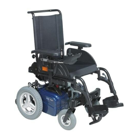
Page 9: Components
Components 4 Components 4.1 Overview Mobility Device Under Rear Shroud Fig. 4-1 A: Drive units B: Power module Under Seat Fig. 4-2 C: Manual wheel lock D: Safety latches for seat E: Battery boxes Special Features Fig. 4-3 F: Scissor system G: Swinging axle H: Kerb climber 1577880-D... - Page 10 Invacare® Fox Modulite Seat Options Fig. 4-4 J: Actuator module (ACT200) under seat plate. 1577880-D...
-
Page 11: Setup
4. Check that swivel casters can move freely. 5. Repeat steps two to four, if necessary. 5.2.1 Adjusting Lower Leg Length Invacare offers a range of legrests which can be adjusted individually. See user manual. 5.3 Adjusting Seat Depth A: Seat depth B: Center of gravity of the seat/ seat position 5.4 Adjusting Seat Depth via Backrest Unit... -
Page 12: Adjusting Seat Height
Invacare® Fox 1. Disconnect cable connections. 2. Loosen and remove nut F plain washer E, saddle washer D, rosette B and bolt A. 3. Position backrest mounting bracket G according to seat depth, so that holes on seat frame C and backrest mounting bracket G are in line. -
Page 13: Adjusting Seat Height Via Seat Support
Setup Fig. 5-1 Seat height can be set to two different seat heights using scale B. Adjust seat height according to following table: 480 mm Use left scale (default value: 4) 510 mm Use right scale (default value: 4) 1. Remove seat. See 7.10.1 Moving Seat Into Service Position / Removing Seat, page 44. 2. - Page 14 Invacare® Fox WARNING! The seating system of the mobility device is delivered ex works with an optimally adjusted centre of gravity (CoG). Any change in this adjustment setting can negatively influence the stability of the mobility device. – You must perform an individual risk analysis every time you change the centre of gravity of the seating position, in order to ensure the safety and stability of the mobility device.
-
Page 15: Adjusting Safety Latch
Setup 1. Remove seat. See 7.10.1 Moving Seat Into Service Position / Removing Seat, page 44. 2. Loosen and remove four bolts B, washers C and nuts D on both sides. 3. Shift position of seat. 4. Align holes on seat frame and seat support and insert bolts. 5. -
Page 16: Testing
4. If there is a defect, replace motor and send it to Invacare Service for inspection or repair. Fig. 6-2 DuraWatt motor serves as an example. 6.3 Rain test •... -
Page 17: Field Load Test
Testing 6.4 Field Load Test Old batteries loose their ability to store and release power due to increased internal resistance. In this procedure, batteries are tested under load using a digital voltmeter to check battery charge level at the charger connector. The charger connector is located on the remote. - Page 18 Invacare® Fox DON’T Don’t use chargers or batteries that are not appropriate Follow recommendations in this manual when selecting for the chair. a battery or charger. Don’t put new batteries into service before charging. Fully charge a new battery before using.
-
Page 19: Service
Service 7 Service 7.1 General Warning Information on Installation Work CAUTION! Risk of damage to vehicle Collisions can be caused if the adjusting washers are removed during fitting work to the drive wheels. Adjusting washers are often fitted between the drive shaft and the wheel hub to even out tolerances. If these adjusting washers are removed and not replaced again, collisions can be caused. - Page 20 Invacare® Fox Component Notes Check Remedy Wheel suspension and Check drive wheels for Adjust, replace wheel See 7.9 Wheels, page wheels tight fit and side play hubs Check steering wheels Replace wheels, wheel for tight fit, float and fork or wheel bearings...
-
Page 21: Troubleshooting
The power modules used are described in the corresponding controls manual. The tables for rectification of operational faults listed in the following chapters are only an excerpt from the original manufacturer's manuals. You can obtain the original manuals from Invacare. 7.4.2 Drive fault diagnosis Problem... -
Page 22: Chassis
Invacare® Fox 7.5 Chassis 7.5.1 Changing Wheelbase • 5 mm Allen key • 10 mm wrench 1. Remove seat. See 7.10.1 Moving Seat Into Service Position / Removing Seat, page 44. 2. Loosen and remove bolt and nut C. 3. Adjust centre column. -
Page 23: Replacing Kerb Climber (L-Shape Lever)
Service WARNING! Risk of injury due to uncontrolled movement of mobility device – Turn off power. – Engage motors. – Secure mobility device against rolling away by placing wedges under wheels. CAUTION! Risk of injury from swinging axle coming loose If swinging axle is insufficiently secured, it can come loose when driving. -
Page 24: Replacing Rubber Foot
Invacare® Fox Removing Kerb Climber 1. Secure mobility device against rolling away. 2. If necessary, remove parts that are in the way like legrests or swinging axle. 3. Loosen and remove screw D. 4. Pull gas spring C out of holder. -
Page 25: Replacing Rubber Stopper
Service 7.5.5 Replacing Rubber Stopper We recommend to replace all rubber stoppers as soon as one needs replacing. • 10 mm wrench Fig. 7-1 Removing Rubber Stopper 1. Remove swinging axle. See 7.5.2 Replacing / Reversing Swinging Axle, page 22. 2. -
Page 26: Shrouds
Invacare® Fox Removing Motor / Gearbox Unit 1. Remove rear shroud. See 7.7 Shrouds, page 26. 2. Lift mobility device on one side and place a 14 cm high wooden block underneath it so that drive wheel is off ground and can rotate freely. -
Page 27: Battery Shroud
Service Removing Rear Shroud 1. Remove cable tie from bus cable in notch B right or left. 2. Loosen and remove two screws D including washer C on rear shroud A. 3. Pull rear shroud carefully away from chassis. Installing Rear Shroud 1. -
Page 28: Electrical Components
– Changes to the drive program may only be carried out by trained providers. – Invacare can only give a warranty for safe mobility device driving behaviour - especially the tipping stability - for unaltered standard drive programs. -
Page 29: Replacing Batteries
Service CAUTION! Fire and burns hazard if battery terminal is bypassed – Take great care to ensure that the battery terminals are never short-circuited with tools or mechanical mobility device parts. – Ensure that the battery terminal caps have been replaced if you are not working on the battery terminals. CAUTION! Risk of crushing Batteries can be extremely heavy. -
Page 30: Installing / Removing Battery Boxes
Invacare® Fox 3. Remove battery boxes. See 7.8.4 Installing / Removing Battery Boxes, page 30. 4. Remove handle and shroud of battery box. See 7.7.2 Battery Shroud, page 27. 5. Loosen and remove bolt A, washer E and nut F on both sides of battery C. -
Page 31: Replacing Remote
Every alteration to the drive program can influence handling and tipping stability of mobility device. – Alterations to drive program must only be carried out by trained Invacare® providers. – Invacare® can only assume a warranty for safe handling of mobility device – in particular tipping stability - for unaltered standard drive programs. -
Page 32: Tyre Types
Invacare® Fox 7.9.2 Tyre Types There are three different types of tyres or inner tubes, and specific points must be observed for the replacement of each type. The individual types of tyres can be easily distinguished: • Pneumatic tyres have black valve caps. -
Page 33: Overview Of Power Wheelchair Models And Wheel Types
Service Castor Wheels 6” 8” 9” 10” Wheel 18 Nm 18 Nm 25 Nm 16 Nm 16 Nm 25 Nm 25 Nm 25 Nm 18 Nm 100 Nm Fixation 5 Nm — — — 5 Nm 10 Nm 25 Nm 25 Nm 25 Nm 25 Nm... - Page 34 Invacare® Fox Models Drive wheels 10” x 3” 12 1/2” x 2 1/4” 14” 4–Spoke 3–Spoke 5–Spoke 5–Spoke 3–Spoke 5–Spoke 5–Spoke 5–Spoke Solid Rim Plas- Rim for (5–screw (1–Bolt (1–Bolt (1–Bolt tic Rim (1–Bolt (1–Bolt (5–Screw True installa- Installa- Installa- Installa- (1–Bolt...
-
Page 35: Replacing Drive Wheel (1-Bolt Installation)
Service Models Castor Wheels 6” 8” 9” 10” Single- Double-Sided Fork Single- Double- Single- Double- Single- Sided/ Sided/ Sided Sided/ Sided Sided Double- Double- Fork Double- Fork Fork Sided Sided Sided Fork Fork Fork Pronto AVIV- A RX * For wheelchair-specific mounting instruction, see respective manual. 7.9.5 Replacing Drive Wheel (1-Bolt Installation) This chapter deals with drive wheels that are installed with one central bolt. -
Page 36: Replacing Manual Wheel Lock
Invacare® Fox Installing Wheel 1. Install parts in reverse order. 2. When installing wheel, pay attention to correct direction of rotation. 3. Tighten nut to prescribed torque. See 7.9.3 Specific Tightening Torques, page 32. Replacing Wheel (10” x 3”) •... -
Page 37: Replacing Castor Wheel On Double-Sided Fork
Service 7.9.7 Replacing Castor Wheel on Double-Sided Fork • 5 mm Allen key • 13 mm wrench • Oblong wooden block (at least 14 x 14 x 30 cm) • 13 mm wrench (2x) • Oblong wooden block (at least 14 x 14 x 30 cm) •... - Page 38 Invacare® Fox Replacing Castor Wheel (Aviva RX and Storm Max) • 5 mm Allen key (up to August 2016) • TX40 Torx key (starting August 2016) • Oblong wooden block (at least 14 x 14 x 30 cm) Removing Wheel 1.
-
Page 39: Replacing Tyres
Service Installing Wheel 1. Install parts in reverse order. 2. When installing wheel, pay attention to correct direction of rotation. 3. Tighten nut to prescribed torque. See 7.9.3 Specific Tightening Torques, page 32. 7.9.8 Replacing Tyres Repairing Pneumatic and Puncture-Protected Tyres •... -
Page 40: Replacing Front Fork
Invacare® Fox 8. Install tyre in reverse order. 9. Apply rim halves to wheel. 10. Inflate tyre a little. 11. Place screws in wheel rim and tighten screws with prescribed torque. Make sure that inner tube is not clamped between wheel rim halves. -
Page 41: Replacing Caster Locks
Service Fig. 7-14 Removing Fork 1. Remove plastic cap A. 2. Loosen and remove nut B, curved spring washer C and plain washer D. 3. Pull fork E out of steering head. Installing Fork 1. Install parts in reverse order. 2. -
Page 42: Replacing Anti-Tipper Wheels
Invacare® Fox Fig. 7-15 Removing Caster Lock 1. Remove legrests and other parts that are in the way. 2. Unlock caster locks C for front wheels on swinging axle A. 3. Remove front fork. See 7.9.9 Replacing Front Fork, page 40. -
Page 43: Replacing Steering Head Bearings On Steering Wheels
Service 7.9.12 Replacing Steering Head Bearings on Steering Wheels CAUTION! Incorrect installation can damage bearings and cause steering wheels to fall out. The single-row angular ball bearing rings are not identical on both sides. There is only one correct way to insert them. -
Page 44: Installing Ball Bearings
Installing Seat 1. Place seat vertically onto its holder again. 2. Fold seat forward. 3. Make sure safety latches A on centre post engage. 7.10.2 Replacing Seat Frame (Fox Seat) • Phillips screwdriver, size 2 • 5 mm Allen key •... - Page 45 Service When removing, take care of small parts such as screws and washers. Put all small parts down so that they can be installed in correct sequence. Fig. 7-19 Removing Seat Frame 1. Remove any tie wraps which may have been fitted to hold cable away from remote. Remove cable from glued terminals.
-
Page 46: Replacing Fabric Seat (Padded)
Invacare® Fox 7.10.3 Replacing Fabric Seat (Padded) • Phillips screwdriver, size 2 Removing fabric seat In older revisions of the seat, the last bolt on each side adjust the backrest adapter. This seat can look different to the image above. -
Page 47: Replacing Seat Plate
Service Installing Fabric Seat Fig. 7-23 1. Position backrest mounting bracket D according to seat depth, so that holes of bracket and seat frame are in line. See 5.4 Adjusting Seat Depth via Backrest Unit, page 11. 2. Slightly tighten set screws hand-tight. 3. -
Page 48: Replacing Safety Latch
19 mm wrench • 12 mm wrench Removing safety latch 1. Remove seat frame. See 7.10.2 Replacing Seat Frame (Fox Seat), page 44. 2. Loosen adjusting nut B. 3. Unscrew safety latch A and replace it. Installing safety latch 1. Install parts in reverse order. -
Page 49: Backrest
Service 1. Loosen and remove bolts E including washers F, mounting plate D and bottom side of bracket C. 2. Remove top side of bracket B including nuts A. Fig. 7-25 Installing Bracket 1. Install parts in reverse order. 2. Test all functions. 7.12 Backrest 7.12.1 Replacing Standard Backrest •... -
Page 50: Armrests
Invacare® Fox Fig. 7-26 Removing Backrest Holder 1. Remove backrest unit. See 7.12.1 Replacing Standard Backrest, page 49. 2. Loosen and remove nut A and washer B. 3. Remove bolt H, nut G, washers F and bushing D. 4. Pull quick release cord K to unlock backrest holder E. -
Page 51: Installing Inrigged Armrest (Wooden Seat Plate)
Service Removing armrest 1. Loosen two screws B. 2. Pull armrest C out of the holder. Installing armrest 1. Install parts in reverse order. 2. Test all functions. 7.13.2 Installing Inrigged Armrest (Wooden Seat Plate) • 3 mm Allen key You must insert a spacer when mounting inrigged armrests to a wooden seat plate. -
Page 52: Replacing Foot Plate / Heel Strap Of Legrest
Invacare® Fox Removing Holder 1. Loosen screw B. 2. Pull holder C out of seat frame A. 3. Replace holder. Installing Holder 1. Install parts in reverse order. 2. Test all functions. 7.14 Replacing Foot Plate / Heel Strap of Legrest •... -
Page 53: Lighting Unit
Service Fig. 7-31 Removing Posture Belt 1. Remove plastic cap A. 2. Loosen and remove bolt F nut B, washers C and distance bushing E. 3. Remove posture belt. 4. Repeat all steps on other side. Installing Posture Belt 1. Install parts in reverse order. 2. - Page 54 Notes...
- Page 55 Notes...
- Page 56 Invacare Sales Companies Australia: Canada: Ireland: New Zealand: Invacare Australia Pty. Ltd. Invacare Canada L.P. Invacare Ireland Ltd, Invacare New Zealand Ltd 1 Lenton Place, North Rocks NSW 570 Matheson Blvd East, Unit 8 Unit 5 Seatown Business Campus 4 Westfield Place, Mt Wellington 1060 2151 CDN Mississauga, On.
Need help?
Do you have a question about the Fox and is the answer not in the manual?
Questions and answers