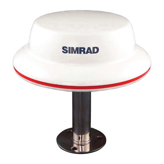
Summary of Contents for Simrad MX521B GPS
- Page 1 MX521B GPS/DGPS Smart Antenna Installation Manual ENGLISH www.navico.com/commercial...
-
Page 3: Preface
Preface Disclaimer As Navico is continuously improving this product, we retain the right to make changes to the product at any time which may not be reflected in this version of the manual. Please contact your nearest distributor if you require any further assistance. It is the owner’s sole responsibility to install and use the equipment in a manner that will not cause accidents, personal injury or property damage. - Page 4 Important notice ¼ Note: The MX521B GPS/DGPS sensor is an aid to navigation only. Its accuracy can be affected by many factors such as equipment defects, environmental conditions, or improper operation. The user is responsible for safe navigation of the vessel. This includes exercising common prudence and navigational judgement at all times.
-
Page 5: Table Of Contents
Contents Preface General Supplied equipment List of abbreviations Installation Antenna mounting guidelines Antenna mounting Wiring Technical specifications Dimensional drawings Contents | MX521B Installation Manual... -
Page 6: General
Before installing the MX521B smart antenna, please read this manual carefully to ensure proper installation and operation of the unit. Supplied equipment Description Part Number MX521B GPS smart antenna with GLONASS 000-11641-001 MX521B DGPS smart antenna with GLONASS 000-11640-001 and beacon differential receiver The antenna cable assembly is not included and must be ordered separately. -
Page 7: List Of Abbreviations
The MX521B GPS and DGPS are combined GPS/DGPS/GLONASS smart antenna sensors. They are fully automatic and do not require initialization or user intervention. They will automatically search for available satellites and make a position fix shortly after power is applied. -
Page 8: Installation
Installation Antenna mounting guidelines The MX521B antenna housing is weather-resistant and must be located outside where it will have a good view of the sky around it. Use a standard 1”-14 TPI bracket or tube for mounting. • Install the antenna where it has a clear view of the sky around it. •... -
Page 9: Antenna Mounting
RADAR ANT. INMARSAT ANT. MAIN MAST VHF OR MF ANT. MX ANT. 10 m MOUNT THE MX521 10 m (min.) FORWARD OF MAIN MAST Antenna mounting Bracket mount The MX521B mounting thread is an industry standard fitting for VHF antenna mounting (1inch, 14 TPI). This enables the antenna to be mounted on a wide range of mounting brackets, including swivel joints, commonly used for angled surface. - Page 10 Surface mount The antenna can also be surface-mounted. Make sure there is at least 5-inch clearance underneath the mounting surface to accommodate the lower section of the antenna housing, connector and cable. Refer to the figure below for surface mounting considerations.
-
Page 11: Wiring
Antenna cable selection The antenna cable assembly for the MX521B antenna is not included in the kit and must be ordered separately. Several cable lengths are available in stock. To assist you in ordering the correct cable length, please refer to the antenna cable list below for cable description and part number. - Page 12 Antenna cable assembly Below is a diagram showing the pins and wire color-coding of the antenna cable assembly. 10-Pin Female connector Antenna cable Assy. Signal Pin# Wire Ext. RTCM IN - Grey Purple Ext. RTCM IN + Beacon Status Out +, Secondary output White Beacon Status Out -, Secondary output Yellow...
- Page 13 Wiring example Ext. RTCM IN - Ext. RTCM IN + Beacon Status Out + To antenna Beacon Status Out - GPS Out +, Primary output GPS Out -, Primary output MPM In +, Control input MPM In -, Control input 2 A fuse 12 / 24 V DC Wire...
- Page 14 Data interface to PC or other navigation systems The figure below shows the power and data output connections to the serial port of a PC or other navigation systems using a dB9 connector and a terminal strip (user supplied items). BRN (MPM In +) BLU (MPM In -) GRN (GPS Out +)
- Page 15 MX521B Programming cable The programming cable is used for upgrading the software of the GPS and Beacon PCBs inside the MX521B smart antenna. The figure below shows the programming cable diagram and equipment setup. Please note that external 12/24 volt DC is required to power up the antenna.
-
Page 16: Technical Specifications
Technical specifications GNSS receiver Type L1, C/A Code (SPS) with carrier phase smoothing Frequency 1575.42 MHz Channels 12 Channels, parallel tracking (10 channels when tracking SBAS) Update rate 1 Hz Signals received GPS and GLONASS Fix calculation GPS or GPS + GLONASS SBAS tracking 2 channel parallel tracking RTCM Input RTCM SC-104 format Antenna type Ceramic patch... - Page 17 Operating current < 230 mA at 12.0 VDC Power consumption < 3 Watts Mechanical Height 102 mm (4.0”) Diameter 182 mm (7.2”) Weight (MX521B DGPS) 820 g Weight (MX521B GPS) 600 g Mounting 1”14 pole mount or surface mounting | 17 Technical specifications | MX521B Installation Manual...
-
Page 18: Dimensional Drawings
Dimensional drawings 182.0 mm (7.17”) 4-40 UCN mounting screws (4 places) 133.35 mm (5.25”) 4-40 UCN mounting screws 18 | Dimensional drawings | MX521B Installation Manual...


Need help?
Do you have a question about the MX521B GPS and is the answer not in the manual?
Questions and answers