Table of Contents
Advertisement
Quick Links
Assembly Notice
Model Name:
GBT P/N:
Release Date:
NOTICE: This document has released under
A Non-Disclosure Agreement to:
CUSTOMER:
PROJECT:
This Document has been released from:
Company:
Approved By:
Checked By:
Released By:
Ref.No/ Rev:
G481-HA0-00
6NG481HA0MR-00-*
2018/07/02
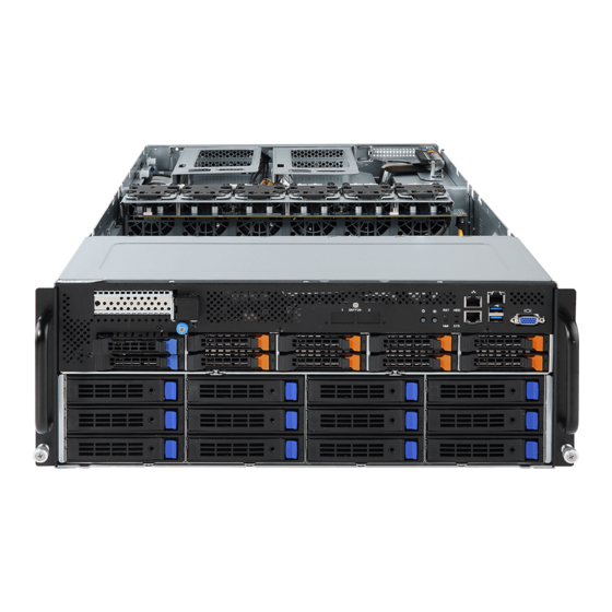
G481-HA0
GIGABYTE TECHNOLOGY CO., LTD
1.0
Advertisement
Table of Contents

Subscribe to Our Youtube Channel
Related Manuals for Gigabyte G481-HA0-00


Summary of Contents for Gigabyte G481-HA0-00
- Page 1 Model Name: G481-HA0-00 GBT P/N: 6NG481HA0MR-00-* Release Date: 2018/07/02 NOTICE: This document has released under A Non-Disclosure Agreement to: CUSTOMER: PROJECT: G481-HA0 This Document has been released from: Company: GIGABYTE TECHNOLOGY CO., LTD Approved By: Checked By: Released By: Ref.No/ Rev:...
-
Page 2: Table Of Contents
System integration Work Instruction engineering department Issued Date: 2018-07/02 Document Ref. Number: Pages: Revision: 0.1 Revised Date: 2/21 Overview ....................3 1.1 Document History ....................3 1.2 Purpose ........................3 1.3 Screw Torque Table ....................4 Procedure for System assembly ............. 5 ... -
Page 3: Overview
1.1 Document History Item Revision Description Date Originator 張建誠 release 2018-07-02 1.2 Purpose This document defines the particular Gigabyte requirements for standard server assembly at DVT stage. The purpose is to ensure the method of assembly be transfer to the factory. -
Page 4: Screw Torque Table
System integration Work Instruction engineering department Issued Date: 2018-07/02 Document Ref. Number: Pages: Revision: 0.1 Revised Date: 4/21 1.3 Screw Torque Table (Suggestion (Screw Spec) (Screwdriver Type) (Remark) Torque) Screw type: M3x5L 5kg/cm0.5 2598EG-1C003-S00... -
Page 5: Procedure For System Assembly
System integration Work Instruction engineering department Issued Date: 2018-07/02 Document Ref. Number: Pages: Revision: 0.1 Revised Date: 5/21 2 Procedure for System assembly Part number / Step Method Q’ty Comment Board model name Remove top cover and take off fan duct, loosen the 40 FAN BKT thumb screw and remove the 40 fan kit. -
Page 6: Step 2
System integration Work Instruction engineering department Issued Date: 2018-07/02 Document Ref. Number: Pages: Revision: 0.1 Revised Date: 6/21 Part number / Step Method Q’ty Comment Board model name Remove the 40 fan kit and open the GPU tray. please keep the Loosen the PCIE BKT screws and take out screws on hand the PCIE BKE. -
Page 7: Step 3
System integration Work Instruction engineering department Issued Date: 2018-07/02 Document Ref. Number: Pages: Revision: 0.1 Revised Date: 7/21 Part number / Step Method Q’ty Comment Board model name Plug in short GPU Power cable with GPGPU Total needs to 25CRI-100002-B0R assembly 8 units 2.3 Step 3 Before plug in the GPGPU power... -
Page 8: Step 4 1St Gpgpu Assembly
System integration Work Instruction engineering department Issued Date: 2018-07/02 Document Ref. Number: Pages: Revision: 0.1 Revised Date: 8/21 Part number / Step Method Q’ty Comment Board model name 4.1 Please follow the arrowhead to insert the GPGPU into GPU fan duct then 4.2 lock it on PCIE/B and fasten it with 2* M3x5L, then 4.3 power cable assembly on GPU Power /B. - Page 9 System integration Work Instruction engineering department Issued Date: 2018-07/02 Document Ref. Number: Pages: Revision: 0.1 Revised Date: 9/21...
-
Page 10: Step 5 2 Nd To 8 Th Gpgpu Assembly
System integration Work Instruction engineering department Issued Date: 2018-07/02 Document Ref. Number: Pages: Revision: 0.1 Revised Date: 10/21 Part number / Step Method Q’ty Comment Board model name 5.1 Please follow the arrowhead to insert the GPGPU into GPU fan duct then 5.2 lock it on PCIE/B and fasten it with 2* M3x5L, then 5.3 power cable assembly on GPU Power /B. - Page 11 System integration Work Instruction engineering department Issued Date: 2018-07/02 Document Ref. Number: Pages: Revision: 0.1 Revised Date: 11/21 to 8 GPGPU assembly please follow 2ndGPGPU card assembly SOP.
-
Page 12: Step 6 9 Th Gpgpu Assembly
System integration Work Instruction engineering department Issued Date: 2018-07/02 Document Ref. Number: Pages: Revision: 0.1 Revised Date: 12/21 Part number / Step Method Q’ty Comment Board model name Put back the GPGPU Tray and take off the please keep the M3x5L screws on the tray top. -
Page 13: Step 7
System integration Work Instruction engineering department Issued Date: 2018-07/02 Document Ref. Number: Pages: Revision: 0.1 Revised Date: 13/21 Part number / Step Method Q’ty Comment Board model name Take off the screws from GPU BKT and please keep the takeoff the PCIE BKT screws on hand Plug in the long GPU Power cable with 25CRI-300002-B0R... -
Page 14: Step 9
System integration Work Instruction engineering department Issued Date: 2018-07/02 Document Ref. Number: Pages: Revision: 0.1 Revised Date: 14/21 Part number / Step Method Q’ty Comment Board model name Please follow the arrowhead to insert the GPGPU into GPU BKT and fasten 2 x pcs M3x5L screws 2.9 Step 9... -
Page 15: Step 10
System integration Work Instruction engineering department Issued Date: 2018-07/02 Document Ref. Number: Pages: Revision: 0.1 Revised Date: 15/21 Part number / Step Method Q’ty Comment Board model name When done the GPU to assembly it with BKT, put it on tray and fasten it with 3pc M3 x 5L screws. -
Page 16: Th Gpgpuassembly
System integration Work Instruction engineering department Issued Date: 2018-07/02 Document Ref. Number: Pages: Revision: 0.1 Revised Date: 16/21 Board model name Take of the M3x5L screws from GPU BKT please keep the tray screws on hand 2.11 Step 11- 10th GPGPU assembly... -
Page 17: Step 12
System integration Work Instruction engineering department Issued Date: 2018-07/02 Document Ref. Number: Pages: Revision: 0.1 Revised Date: 17/21 Part number / Step Method Q’ty Comment Board model name Take off the GPU BKT screws and take off please keep the the PCIE BKT. -
Page 18: Step 14
System integration Work Instruction engineering department Issued Date: 2018-07/02 Document Ref. Number: Pages: Revision: 0.1 Revised Date: 18/21 Part number / Step Method Q’ty Comment Board model name Follow the arrowhead to make GPU insert into GPU BKT, and fasten it with 2pcs M3x5L screws. -
Page 19: Step 15
System integration Work Instruction engineering department Issued Date: 2018-07/02 Document Ref. Number: Pages: Revision: 0.1 Revised Date: 19/21 Part number / Step Method Q’ty Comment Board model name When done the GPU to assembly it with BKT, put it on tray and fasten it with 3pc x 5L screws. -
Page 20: Step 16
System integration Work Instruction engineering department Issued Date: 2018-07/02 Document Ref. Number: Pages: Revision: 0.1 Revised Date: 20/21 Board model name Assembly the 40 Fan kit and fasten it with Thumb screws then put the fan cable with clip then trim it. 2.16 Step 16... -
Page 21: Step 17
System integration Work Instruction engineering department Issued Date: 2018-07/02 Document Ref. Number: Pages: Revision: 0.1 Revised Date: 21/21 Part number / Step Method Q’ty Comment Board model name 17 Put back the fan duct back to system 2.17 Step 17...
Need help?
Do you have a question about the G481-HA0-00 and is the answer not in the manual?
Questions and answers