Range Road RR5026 Owner's Manual
Saw mill
Hide thumbs
Also See for RR5026:
- Owner's manual (35 pages) ,
- Owner's manual (38 pages) ,
- Owner's manual (38 pages)
Table of Contents
Advertisement
Range Road RR5026 & RR5029 Saw Mill
WARNING:
Read carefully and understand all ASSEMBLY AND OPERATION INSTRUCTIONS before
operating. Failure to follow the safety rules and other basic safety precautions may result in
serious personal injury.
Range Road Enterprises Ltd
Box 944
Eckville AB T0M 0X0
www.range-road.ca
Owner's Manual
Advertisement
Table of Contents

Related Manuals for Range Road RR5026


Summary of Contents for Range Road RR5026
- Page 1 Range Road RR5026 & RR5029 Saw Mill Owner’s Manual WARNING: Read carefully and understand all ASSEMBLY AND OPERATION INSTRUCTIONS before operating. Failure to follow the safety rules and other basic safety precautions may result in serious personal injury. Range Road Enterprises Ltd...
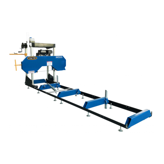
- Page 2 INTENDED USE The Range Road Saw Mill is portable and versatile which makes it a great tool for any lumber project. It has the capabilities of sawing logs up to 26” or 29” in diameter, 7” thick and a cutting length of 125”. It is equipped with a 15HP RT Brand Engine or a 13.5HP Briggs &...
- Page 3 Store idle saw mill. When saw mill is not in use, store it in a secure place out of the reach of children. Inspect it for good working condition prior to storage and before re-use. Range Road Enterprises Ltd Box 944 Eckville AB T0M 0X0 www.range-road.ca...
- Page 4 Engine exhaust contains carbon monoxide. This is a poison you cannot see or smell. NEVER use gas engines indoors EVEN IF doors and window are open. Only use OUTSIDE and far away from windows, doors and vents. Range Road Enterprises Ltd Box 944 Eckville AB T0M 0X0 www.range-road.ca...
- Page 5 Caution is necessary when near the engine’s magneto or recoil starter. 6) Use only accessories that are recommended by Range Road for your model. Accessories that may be suitable for one piece of equipment may become hazardous when used on another piece of equipment.
- Page 6 Maintain all labels on the saw mill. These show important information. If unreadable, missing or damaged, contact Range Road for a replacement. Have the equipment serviced by a qualified repair person using only OEM replacement parts. This will ensure that the safety of the saw mill is maintained.
- Page 7 2) The two long boxes at the bottom of the crate are the rail parts. Open these boxes and you will see a small white box, open and take out the bolts and nuts for mounting the rails. Range Road Enterprises Ltd Box 944 Eckville AB T0M 0X0 www.range-road.ca...
- Page 8 4) Place the 2 rails on their levelling feet parallel to each other, for the RR5026 sawmill the measurement from outside rail to outside rail needs to be 845mm (33 ¼”) for the RR5029 sawmill the measurement from outside rail to outside rail needs to be 902mm (35 ½”) For any Sawmill to cut square and straight all pieces have to be squared to each other and level.
- Page 9 6) Check your width measurement again 26” -845mm (33 1/4”) or 29” - 902mm (35 1/2”) 7) Do cross measurements now to make sure the rails are square to each other. Range Road Enterprises Ltd Box 944 Eckville AB T0M 0X0...
- Page 10 The RR5026 should be 2217mm (86 7/8”) across from either corner The RR5029 should be 2240mm (88 1/8”) across from either corner 8) When the rails are square, tighten all 8 bolts in the log support cross tubes and recheck levelness and squareness, adjust as needed.
- Page 11 13) Check to make sure rails are the correct distance apart at both ends and put on the end log support cross tube, do not tighten the bolts. 14) Cross measure new rails and adjust RR5026 2217mm (86 7/8”) RR5029 2240mm (88 1/8”) Range Road Enterprises Ltd...
- Page 12 17) Cut the cardboard at the base of the tube so they can go through to the floor Range Road Enterprises Ltd Box 944 Eckville AB T0M 0X0...
- Page 13 20) Place the top frame upside down and put the 2 galvanized corner posts in and tighten all 4 corner bolts 21) Tighten all 4 corner bolts to hold posts in place. Range Road Enterprises Ltd Box 944 Eckville AB T0M 0X0...
- Page 14 23) Put the back cover in position and put both bolts in on the side away from the water tank bracket. 24) Put the back cover on the water tank side and put the bolts in Range Road Enterprises Ltd Box 944 Eckville AB T0M 0X0 www.range-road.ca...
- Page 15 25) Place spacers and pulleys on bottom bolts, pulley circlips face the spacers, put nuts and washers on but do not tighten up. 26) Lift complete head unit out of crate Range Road Enterprises Ltd Box 944 Eckville AB T0M 0X0...
- Page 16 27) Mount left and right roller assemblies onto the galvanized tubes, snug bolts up but do not tighten them. 28) Position head unit over track and line rollers up so that the track sits in the roller groove, set head unit onto tracks. Range Road Enterprises Ltd Box 944 Eckville AB T0M 0X0...
- Page 17 29) Tighten all 8 bolts on roller frames 30) Tighten 8 bolts on top frame of head unit Install roller stops at all 4 frame corners Range Road Enterprises Ltd Box 944 Eckville AB T0M 0X0 www.range-road.ca...
- Page 18 33) Tighten bolt in water tank mount bracket and put water tank in, the copper end on the water tank hose runs through the hole in the frame above the blade, loosen the 16mm bolt, put the copper tube through, aiming it towards the blade and snug the bolt up. Range Road Enterprises Ltd Box 944 Eckville AB T0M 0X0...
- Page 19 35) Wind the lift handle so that the pulley arms are all the way in, then find the two stubs on the inside of the top plate behind the pulley arm, place a cable loop over 1 stub and run cable around pulleys and down to head unit. Range Road Enterprises Ltd Box 944 Eckville AB T0M 0X0...
- Page 20 36) Run threaded rod through the angle bracket on each side of the head unit and tighten the cables up. Range Road Enterprises Ltd Box 944 Eckville AB T0M 0X0 www.range-road.ca...
- Page 21 Measure distance from the blade log support on each side to double check that head unit is level. 37) Install log holder into frame rails, There are multiple frame holes for mounting, choose the one that works best Range Road Enterprises Ltd Box 944 Eckville AB T0M 0X0...
- Page 22 38) Install T-handles into track cross supports to hold the log supports in place, adjust bracket on head unit so that the blade is protected if the head is lower than the log support Range Road Enterprises Ltd Box 944 Eckville AB T0M 0X0 www.range-road.ca...
- Page 23 Continue making small adjustments until the Blade stays centered. AFTER any adjustment, tighten Bolts 96A and 96B and nuts 98A and 98B. 39) Install Throttle control (40) on Push Handle (46) as shown in Figure Q. Figure Q: Throttle Control Range Road Enterprises Ltd Box 944 Eckville AB T0M 0X0 www.range-road.ca...
- Page 24 Cable. Anchor Bolts (159) until the distance between the ends of the Blade and the top of the Middle Support (8) are the same as shown in Figure S. NOTE: Use a tape measure to verify distances. Figure S: Blade Adjustment Range Road Enterprises Ltd Box 944 Eckville AB T0M 0X0 www.range-road.ca...
- Page 25 D) Read the Equipment Operation section that follows 1. Start and operate the engine according to the provided engine manual. 2. Replacement engine operating instructions can be obtained from the engine manufacturer. Range Road Enterprises Ltd Box 944 Eckville AB T0M 0X0...
- Page 26 NOTE: Make sure the Log Clamp Assembly (20) does NOT interfere with the Saw Blade when sawing. The Log Clamp Assembly (20) should be lower than the Saw Blade at all times. Range Road Enterprises Ltd Box 944 Eckville AB T0M 0X0...
- Page 27 16. Adjust the Throttle to bring the Blade up to speed. The Locking Ring can be turned to lock the throttle in place. Figure W: Throttle Control 17. Throttle speed may need to be increased when the Saw is under load. Range Road Enterprises Ltd Box 944 Eckville AB T0M 0X0...
- Page 28 4. Cover and store in dry, well-ventilated area out of reach of children. 5. For cold weather operation, store the equipment in a cool dry area to prevent condensation and premature wear. Range Road Enterprises Ltd Box 944 Eckville AB T0M 0X0...
- Page 29 Remove stray branches that prevent Teeth filled with debris. proper positioning. 4. Clean debris off blade. Follow all safety precautions whenever diagnosing or servicing the equipment or engine. Range Road Enterprises Ltd Box 944 Eckville AB T0M 0X0 www.range-road.ca...
- Page 30 Parts List Range Road Enterprises Ltd Box 944 Eckville AB T0M 0X0 www.range-road.ca...
- Page 31 Range Road Enterprises Ltd Box 944 Eckville AB T0M 0X0 www.range-road.ca...
- Page 32 Range Road Enterprises Ltd Box 944 Eckville AB T0M 0X0 www.range-road.ca...
- Page 33 Range Road Enterprises Ltd Box 944 Eckville AB T0M 0X0 www.range-road.ca...
- Page 34 Range Road Enterprises Ltd Box 944 Eckville AB T0M 0X0 www.range-road.ca...
- Page 35 Note: Some parts are listed and shown for illustration purposed only, and are not available individually as replacement parts. WARRANTY One-year limited warranty For technical questions, please visit www.range-road.ca www.range-road.com Range Road Enterprises Ltd Box 944 Eckville AB T0M 0X0 www.range-road.ca...
Need help?
Do you have a question about the RR5026 and is the answer not in the manual?
Questions and answers