Advertisement
Quick Links
Advertisement

Related Manuals for NexTraq VT-4226


Summary of Contents for NexTraq VT-4226
- Page 1 NexTraq VT-4226 Driver ID Quick Install Guide...
- Page 2 NexTraq. Information and specifications contained in this document are subject to change without notice and do not represent commitments on the part of NexTraq. Under copyright laws, no part of this installation guide may be reproduced or transmitted in any form or by...
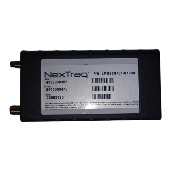
- Page 3 Figure 1: The VT-4226...
- Page 4 Figure 2: VT-4226 power harness Figure 3: VT-4226 and power harness...
- Page 5 Figure 4: Driver ID button Figure 5: 2-pin driver ID connection to harness...
- Page 6 Figure 6: Driver ID alarm Figure 7: 3-pin alarm connection to harness...
- Page 7 Figure 8: The VT-4226 combo antenna Figure 9: Unit connected to antenna. Top: comm; Bottom: GPS.
- Page 8 Figure 10: VT-4226 electrical wiring from power harness. Red: constant power; white: ignition; black: ground...
- Page 9 Figure 11: Button inserted into a dummy panel. White washer on button side, black washer on lock side. Figure 12: Close-up of black washer/wire side of dummy panel.
- Page 10 Figure 13: Close-up of white washer/button side of dummy panel.
- Page 11 Figure 14: Button installed into dummy panel. This should be located as close to the ignition as possible. Figure 15: Alarm mounted in vehicle.
- Page 12 Figure 16: Key fob. Alarm will sound while ignition is on until driver logs in with fob. Fob and button must make contact. Customer will need to record which key fob is assigned to which driver.
-
Page 13: Appendix A - Technical Specifications
Appendix A – Technical Specifications Communication Specifications GSM/GPRS Quad-Band 850/900/1800/1900 MHz GSM/GPRS Output Power 850: 2 Watts (Class 4) 900: 2 Watts (Class 4) 1800: 1 Watt (Class 1) 1900: 1 Watt (Class 1) CDMA Dual-Band 800/1900 MHz CDMA Output Power 800: +24 dBm 800:... -
Page 14: Appendix B - Installation Notes
Appendix B – Installation Notes The first choice for power connections should always be at the ignition column. An industry standard poke-tape-tie-wrap method should be used to secure connections. If column is unobtainable or there is too many other devices wired to the column, then going to the input wires behind the fuse box can be a valid alternative.
Need help?
Do you have a question about the VT-4226 and is the answer not in the manual?
Questions and answers