Table of Contents
Advertisement
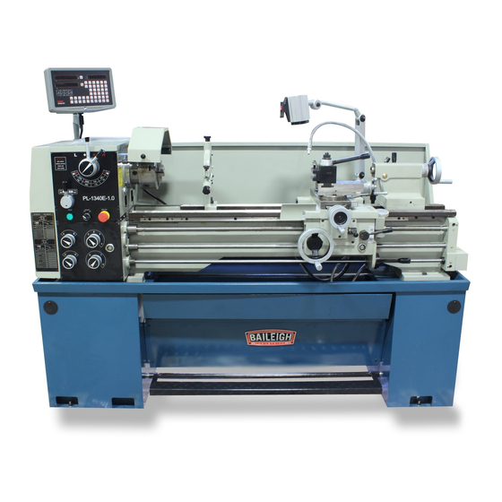
OPERATOR'S MANUAL
METAL LATHE
MODEL: PL-1340E-1.0
Baileigh Industrial, Inc.
P.O. Box 531
Manitowoc, WI 54221-0531
Phone: 920.684.4990
Fax: 920.684.3944
sales@baileigh.com
REPRODUCTION OF THIS MANUAL IN ANY FORM WITHOUT WRITTEN APPROVAL OF BAILEIGH INDUSTRIAL, INC.
IS PROHIBITED. Baileigh Industrial, Inc. does not assume and hereby disclaims any liability for any damage or loss
caused by an omission or error in this Operator's Manual, resulting from accident, negligence, or other occurrence.
Rev. 06/2017
© 2017 Baileigh Industrial, Inc.
Advertisement
Table of Contents

Related Manuals for Baileigh PL-1340E-1.0


Summary of Contents for Baileigh PL-1340E-1.0
- Page 1 REPRODUCTION OF THIS MANUAL IN ANY FORM WITHOUT WRITTEN APPROVAL OF BAILEIGH INDUSTRIAL, INC. IS PROHIBITED. Baileigh Industrial, Inc. does not assume and hereby disclaims any liability for any damage or loss caused by an omission or error in this Operator’s Manual, resulting from accident, negligence, or other occurrence.
-
Page 2: Table Of Contents
Table of Contents THANK YOU & WARRANTY ..................1 INTRODUCTION ......................3 GENERAL NOTES ......................3 SAFETY INSTRUCTIONS ....................4 SAFETY PRECAUTIONS ....................7 Dear Valued Customer: ....................7 TECHNICAL SUPPORT ....................9 TECHNICAL SPECIFICATIONS ................... 10 UNPACKING AND CHECKING CONTENTS ..............11 Cleaning ........................ - Page 3 Cross slide Hand Wheel .................... 32 Spindle Rotation Control .................... 32 Tool Post and Holder ....................32 Tailstock Controls ...................... 33 TEST RUN ........................33 MACHINE ADJUSTMENTS ..................34 Saddle Gib ......................... 34 Cross-Slide Gib ......................35 Compound Gib ......................35 Tail Stock Bed Clamp ....................
-
Page 4: Thank You & Warranty
THANK YOU & WARRANTY Thank you for your purchase of a machine from Baileigh Industrial. We hope that you find it productive and useful to you for a long time to come. Inspection & Acceptance. Buyer shall inspect all Goods within ten (10) days after receipt thereof. Buyer’s payment shall constitute final acceptance of the Goods and shall act as a waiver of the Buyer’s rights to inspect or... - Page 5 Baileigh Industrial makes every effort to ensure that our posted specifications, images, pricing and product availability are as correct and timely as possible. We apologize for any discrepancies that may occur. Baileigh Industrial reserves the right to make any and all changes deemed necessary in the course of business including but not limited to pricing, product specifications, quantities, and product availability.
-
Page 6: Introduction
After receiving your equipment remove the protective container. Do a complete visual inspection, and if damage is noted, photograph it for insurance claims and contact your carrier at once, requesting inspection. Also contact Baileigh Industrial and inform them of the unexpected occurrence. Temporarily suspend installation. -
Page 7: Safety Instructions
IMPORTANT PLEASE READ THIS OPERATORS MANUAL CAREFULLY It contains important safety information, instructions, and necessary operating procedures. The continual observance of these procedures will help increase your production and extend the life of the equipment. SAFETY INSTRUCTIONS LEARN TO RECOGNIZE SAFETY INFORMATION This is the safety alert symbol. - Page 8 SAVE THESE INSTRUCTIONS. Refer to them often and use them to instruct others. PROTECT EYES Wear safety glasses or suitable eye protection when working on or around machinery. PROTECT AGAINST NOISE Prolonged exposure to loud noise can cause impairment or loss of hearing.
- Page 9 HIGH VOLTAGE USE CAUTION IN HIGH VOLTAGE AREAS. DO NOT assume the power to be off. FOLLOW PROPER LOCKOUT PROCEDURES. EMERGENCY STOP BUTTON In the event of incorrect operation or dangerous conditions, the machine can be stopped immediately by pressing the E-STOP button. Twist the emergency stop button clockwise (cw) to reset.
-
Page 10: Safety Precautions
Baileigh does not recommend or endorse making any modifications or alterations to a Baileigh machine. Modifications or alterations to a machine may pose a substantial risk of injury to the operator or others and may do substantial damage to the machine. - Page 11 7. Never leave adjustment tools or lathe chuck wrenches in the chuck or near any moving part of the machine. They can become dangerous projectiles causing serious personal injury or death. 8. Keep work area clean. Cluttered areas invite injuries. 9.
-
Page 12: Technical Support
(other than die sets and blades). For specific application needs or future machine purchases contact the Sales Department at: sales@baileigh.com, Phone: 920.684.4990, or Fax: 920.684.3944. Note: The photos and illustrations used in this manual are representative only and may not depict the actual color, labeling or accessories and may be intended to illustrate technique only. -
Page 13: Technical Specifications
TECHNICAL SPECIFICATIONS Swing Over Bed 13" (330mm) Swing Over Cross Slide 7.750" (197mm) Swing in Gap 18.750" (477mm) Distance Between Centers 39.36" (1000mm) Width of Bed 7.325" (186mm) Spindle Nose D1-4" Spindle Bore 1.50" (38mm) Spindle Bore Taper Morse #5 Spindle Speeds 8 (70-2000 rpm) Travel of Top Slide... -
Page 14: Unpacking And Checking Contents
UNPACKING AND CHECKING CONTENTS Your Baileigh machine is shipped complete. Separate all parts from the packing material and check each item carefully. Make certain all items are accounted for before discarding any packing material. WARNING: SUFFOCATION HAZARD! Immediately discard any plastic bags and packing materials to eliminate choking and suffocation hazards to children and animals. -
Page 15: Transporting And Lifting
TRANSPORTING AND LIFTING CAUTION: Lifting and carrying operations should be carried out by skilled workers, such as a truck operator, crane operator, etc. If a crane is used to lift the machine, attach the lifting chain carefully, making sure the machine is well balanced. Choose a location that will keep the machine free from vibration and dust from other machinery. -
Page 16: Installation
INSTALLATION IMPORTANT: Consider the following when looking for a suitable location to place the machine: • Overall weight of the machine. • Weight of material being processed. • Sizes of material to be processed through the machine. • Space needed for auxiliary stands, work tables, or other machinery. •... -
Page 17: Lubrication
Lubrication Before putting the lathe into operation, make the following lubrication check. Headstock The bearings of the headstock turn in an oil bath. Ensure that the oil level reaches three quarters of the oil gauge glass. Gear Case Remove the end cover to expose the filling plug. Through it the Shell Tellus 32 is filled to the oil level in the oil gauge glass regularly. -
Page 18: Electrical
ELECTRICAL CAUTION: HAVE ELECTRICAL UTILITIES CONNECTED TO MACHINE BY A CERTIFIED ELECTRICIAN! Check if the available power supply is the same as listed on the machine nameplate. WARNING: Make sure the grounding wire (green) is properly connected to avoid electric shock. DO NOT switch the position of the green grounding wire if any electrical plug wires are switched during hookup. - Page 19 • Improper connection of the equipment-grounding conductor can result in risk of electric shock. The conductor with insulation having an outer surface that is green with or without yellow stripes is the equipment-grounding conductor. If repair or replacement of the electric cord or plug is necessary, do not connect the equipment-grounding conductor to a live terminal.
-
Page 20: Getting To Know Your Machine
GETTING TO KNOW YOUR MACHINE Feed direction selector Tailstock quill traverse handwheel Speed selector (high/low) Feed selector handle 4 Steps speed selector Feed/thread selector handle Tool post clamping lever Forward/reverse switch Compound rest lock Feed rod Cross slide lock Longitudinal traverse handwheel Carriage lock Cross traverse handwheel Compound rest handwheel... -
Page 21: Operation: Symbols For Operation
OPERATION: SYMBOLS FOR OPERATION OPERATION: Symbols for operation Electrical Diametric (danger) pitch thread Module Coolant pitch thread Metric Half nut thread opened Imperial Half nut thread closed Right-hand thread and Longitudinal feed toward The headstock side (Left figure) Left -hand thread and Longitudinal feed toward The headstock side (Right figure) -
Page 22: Steady Rest
Steady Rest The steady rest on this lathe is used to support long, small diameter stock that otherwise could not be turned. The steady rest can also be used in place of the tailstock when access to the cutting tool is required at the outboard end of the piece part. -
Page 23: Follow Rest
Follow Rest The follow rest is typically used for small diameter stock to prevent the piece part from “springing” under pressure from the tool. The follow rests, which are opposite the tool post, act as supports to counter balance the force exerted on the piece part by the tool. The tool and the supports form a triangle around the part to help minimize vibration. -
Page 24: Faceplate
Faceplate The faceplate is used for holding work that cannot be swung between centers because of its shape and dimensions. The T- slots and other openings on its surface provide convenient locations for anchor bolts and clamps to secure the piece part. The faceplate can be mounted to the spindle after removing the chuck. -
Page 25: Lathe Setup
LATHE SETUP WARNING: DO NOT start the lathe until all machine assembly has been completed and you have been properly trained and understand all control functions. When performing machine assembly make sure to follow proper lockout / tagout procedures. Failure to comply could result in accidental starting of the lathe resulting in SERIOUS OPERATOR INJURY OR DEATH. -
Page 26: Chuck Removal
Chuck Removal CAUTION: The Chuck is heavy. Use caution lifting the chuck during removal and installation. If the chuck slips and falls, it can trap and crush hands and fingers between the chuck and the plywood on the bed. 1. Lay a piece of plywood on the lathe bed directly beneath the Spindle chuck. -
Page 27: Four Jaw Chuck Installation Preparation
Four Jaw Chuck Installation Preparation 1. With the 3-jaw chuck removed, take note of how far the camlock studs protrude from the back face of the chuck and note the dimensions. 2. Thread each of the 4-jaw camlock studs into the back of the 4-jaw chuck using the dimension obtained from step 1. -
Page 28: Operating Controls
7. Starting with the first cam, snug up the cams. 8. Finally, recheck and fully tighten all of the cams. OPERATING CONTROLS CAUTION: Always wear proper eye protection with side shields, safety footwear, and leather gloves to protect from burrs and sharp edges. When handling large heavy materials make sure they are properly supported. -
Page 29: Feed Direction
Feed Direction This lathe can cut both left and right while feeding or threading, and across the ways when performing facing operations. The feed direction is controlled with the selection handle. The handle is shown here in the neutral position. When rotated to the left position the apron will move to the left along the bed, as indicated by the arrow, or the cross feed will travel away from the operator. - Page 30 The example feed rate charts to the right show some of the more typical settings that might be used. The chart in (fig. A) 120T shows threads per inch while the chart in (fig. B) shows 1" distance between threads in (mm). Besides changing the selection knobs, you may also need to 60 60 60 40 40 56 40 60 change gears, labeled “a”...
-
Page 31: Changing Gears For Thread Selection
Changing Gears for Thread Selection In order to cut threads as listed in the charts and set the longitudinal feed and crossfeed rates, the gears will need to be changed to match the values shown in the “a” and “b” gear rows of the charts. -
Page 32: Feed Lever
Feed Lever The Feed Selector handle (33) is used to select between the longitudinal and cross slide powered motions. The handle is Feed Selector shown in the pulled out neutral position. (33) Pull up on the pivot handle to engage the longitudinal motion. To get to the cross-slide position from neutral, push in and lower the handle. -
Page 33: Threading Dial Indicator
Threading Dial Indicator The threading dial indicator is located on the right-hand side of the apron. It is used when cutting imperial threads and tells you when to engage the half nut to begin the threading process. The indicator face has eight lines and four numbers printed on the dial. -
Page 34: Thread Cutting Operation
Thread Cutting Operation 120T In order to obtain the desired thread, change gears must be installed correctly, using the values in the charts. Failure to 1" do so will result in incorrect threads. 60 60 60 60 60 56 60 60 1. -
Page 35: Carriage Hand Wheel
Carriage Hand Wheel Rotating the hand wheel clockwise (cw) will move the carriage towards the tailstock. Rotating the hand wheel counterclockwise (ccw) will move the carriage towards the headstock. This is helpful when setting up the lathe for turning or when manual movement is required during turning operations. -
Page 36: Tailstock Controls
Tailstock Controls Side Lock Lever The tailstock primary use is for holding centers and drill chucks. Top Lock Lever Turning the handwheel advances or retracts the barrel in the tailstock. The graduated dial on the handwheel is adjustable. The top lock lever locks the tailstock barrel in place. The side lock lever locks the tailstock in place on the lathe bed. -
Page 37: Machine Adjustments
5. Check the tension of the two V-belts located under the gear cover. You should be able to depress the belts about 1/2” (12.7mm) with normal finger pressure. If they are too tight you could damage the shaft bearing. 6. Select the slowest spindle speed (70 RPM) and let the machine run at that speed for 20 minutes. -
Page 38: Cross-Slide Gib
Cross-Slide Gib The gib on the cross-slide can be adjusted with the screws located at each end. The gib is wedge shaped and by loosening the screw closest to the operator and then tightening the opposite screw, the slide will become looser. Loosening the screw furthest away from the operator and tightening the closer screw will tighten the gib. -
Page 39: Steady Rest
Steady Rest 1. To adjust the steady rest, first loosen the three lock nuts. Setscrew 2. To open the fingers, turn the knurled screws clockwise (cw). If a knurled screw turns hard, back out the Lock Nuts setscrew a little. 3. -
Page 40: Lathe Alignment
Lathe Alignment When the lathe is installed and ready for use, it is recommended to check the machine alignment before beginning work. Alignment and leveling should be checked regularly to insure continued accuracy. 1. Start with a straight steel bar with a diameter of 2.00”... - Page 41 8. To perform a tailstock check, use a 12” (305mm) long ground steel bar fitted between the headstock and the tailstock. 9. Check the alignment by fitting a dial test indicator to the top slide and traversing the centerline of the bar. HEADSTOCK TAILSTOCK 12 in.
-
Page 42: V-Belt Removal And Adjustment
V-Belt Removal and Adjustment Note: Always replace belts as a matched set of two. V-belts will stretch through usage. Check the tension of the belts every three months. More often if the lathe is used daily. 1. Remove the gear cover at the headstock end of the machine to have access to the V-belts. -
Page 43: Lubrication And Maintenance
LUBRICATION AND MAINTENANCE WARNING: Make sure the electrical disconnect is OFF before working on the machine. Maintenance should be performed on a regular basis by qualified personnel. Always follow proper safety precautions when working on or around any machinery. Note: Proper maintenance can increase the life expectancy of your machine. Daily Maintenance •... -
Page 44: Accessing And Cleaning The Coolant System
• Install tank if removed. Oils for Lubricating Coolant Any 10:1 (water to coolant) solution will work, however we recommend Baileigh B-Cool 20:1 (water to coolant) biodegradable metal cutting fluid. It has excellent cooling and heat transfer characteristics, is non-flammable, and extends tool and machine life. Each gallon of concentrate makes 21 gallons of coolant. -
Page 45: Headstock
Headstock The headstock is splash lubricated from an internal reservoir of oil. 1. Ensure that the oil level shows 3/4 full in the oil sight gauge. 2. To drain the oil from the headstock, remove the pipe plug. 3. Fill the headstock reservoir by removing the fill plug. 4. -
Page 46: Gearbox
Gearbox The gearbox is splash lubricated from an internal reservoir of oil. 1. Ensure that the oil level shows 3/4 full in the oil sight gauge. 2. To drain the oil from the gearbox, remove the pipe plug. 3. Fill the headstock reservoir by removing the fill plug. 4. - Page 47 Apply lubricant to the oiler points as indicated daily. Also oil the cross slide nut, lead screw, and slide ways with a light machine oil or way lubricant on a daily basis. Note: Use a bristle paint brush to clean the slide ways, lead screw, and feed shaft. Oiler Points Oiler Point...
-
Page 48: Electrical Diagram
ELECTRICAL DIAGRAM... -
Page 49: Electrical Component List
Electrical Component List Code Name Description Model Technical Data KM1; KM2 A.C. Contactor, Motor Rotation LC1-D189 AC110V, 50/60Hz A.C. Contactor, Coolant Pump LC1-D099 AC110V, 50/60Hz Relay, Power On CA2-DN140 AC110V, 50/60Hz Thermal Relay, Main Motor 9-13A Thermal Relay, Coolant Motor 0.35-0.52A Circuit Breaker, Control DZ47-63... -
Page 50: Thread And Feed Selection
THREAD AND FEED SELECTION Longitudinal and cross feed table. Metric and imperial thread table. Suitable for metric lead crew. Suitable for imperial leadscrew... -
Page 51: Threading Dial Indicator
THREADING DIAL INDICATOR INDICATOR TABLE WHIT WORTH SCALE SCALE SCALE 1.3.5.7 41/2 43/4 1.3.5.7 51/2 1.3.5.7 61/2 1.3.5.7 1.3.5.7 91/2 1.3.5.7 NOTES... - Page 52 BAILEIGH INDUSTRIAL HOLDINGS LLC 1625 D , WI 54220 UFEK RIVE ANITOWOC : 920. 684. 4990 F : 920. 684. 3944 HONE www.baileigh.com BAILEIGH INDUSTRIAL HOLDINGS LTD. U WIFT OINT WIFT ALLEY NDUSTRIAL STATE UGBY , CV21 1QH U IDLANDS...
Need help?
Do you have a question about the PL-1340E-1.0 and is the answer not in the manual?
Questions and answers