Table of Contents
Advertisement
OPERATOR'S
MANUAL
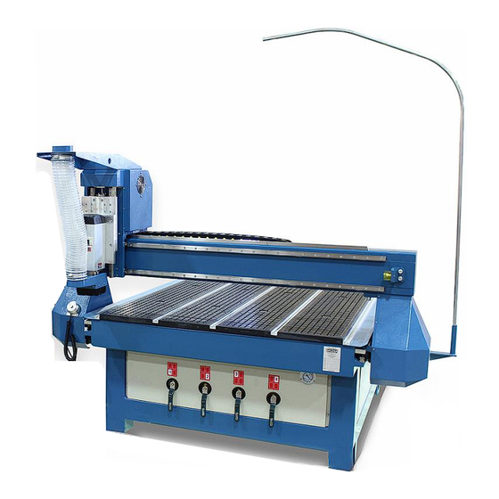
WOOD ROUTER TABLE
MODEL: WR-84V
Baileigh Industrial, Inc.
P.O. Box 531
Manitowoc, WI 54221-0531
Phone: 920.684.4990
Fax: 920.684.3944
sales@baileigh.com
REPRODUCTION OF THIS MANUAL IN ANY FORM WITHOUT WRITTEN APPROVAL OF BAILEIGH INDUSTRIAL, INC.
IS PROHIBITED. Baileigh Industrial, Inc. does not assume and hereby disclaims any liability for any damage or loss
caused by an omission or error in this Operator's Manual, resulting from accident, negligence, or other occurrence.
Rev. 09/2017
© 2017 Baileigh Industrial, Inc.
Advertisement
Table of Contents

Related Manuals for Baileigh WR-84V


Summary of Contents for Baileigh WR-84V
- Page 1 REPRODUCTION OF THIS MANUAL IN ANY FORM WITHOUT WRITTEN APPROVAL OF BAILEIGH INDUSTRIAL, INC. IS PROHIBITED. Baileigh Industrial, Inc. does not assume and hereby disclaims any liability for any damage or loss caused by an omission or error in this Operator’s Manual, resulting from accident, negligence, or other occurrence.
-
Page 2: Table Of Contents
Table of Contents THANK YOU & WARRANTY ..................1 INTRODUCTION ......................3 GENERAL NOTES ......................3 SAFETY INSTRUCTIONS ....................4 SAFETY PRECAUTIONS ....................6 Dear Valued Customer: ....................7 TECHNICAL SUPPORT ....................9 Noise Emission ......................10 Combustion Hazard ....................10 Combustion and Explosion Conditions .............. -
Page 3: Thank You & Warranty
THANK YOU & WARRANTY Thank you for your purchase of a machine from Baileigh Industrial. We hope that you find it productive and useful to you for a long time to come. Inspection & Acceptance. Buyer shall inspect all Goods within ten (10) days after receipt thereof. Buyer’s payment shall constitute final acceptance of the Goods and shall act as a waiver of the Buyer’s rights to inspect or... - Page 4 Baileigh Industrial makes every effort to ensure that our posted specifications, images, pricing and product availability are as correct and timely as possible. We apologize for any discrepancies that may occur. Baileigh Industrial reserves the right to make any and all changes deemed necessary in the course of business including but not limited to pricing, product specifications, quantities, and product availability.
-
Page 5: Introduction
After receiving your equipment remove the protective container. Do a complete visual inspection, and if damage is noted, photograph it for insurance claims and contact your carrier at once, requesting inspection. Also contact Baileigh Industrial and inform them of the unexpected occurrence. Temporarily suspend installation. -
Page 6: Safety Instructions
IMPORTANT PLEASE READ THIS OPERATORS MANUAL CAREFULLY It contains important safety information, instructions, and necessary operating procedures. The continual observance of these procedures will help increase your production and extend the life of the equipment. SAFETY INSTRUCTIONS LEARN TO RECOGNIZE SAFETY INFORMATION This is the safety alert symbol. - Page 7 SAVE THESE INSTRUCTIONS. Refer to them often and use them to instruct others. PROTECT EYES Wear safety glasses or suitable eye protection when working on or around machinery. PROTECT AGAINST NOISE Prolonged exposure to loud noise can cause impairment or loss of hearing.
-
Page 8: Safety Precautions
CUTTING HAZARD Keep hands and fingers away from the rotating shaper cutters. These rotating cutters can be extremely dangerous if you do not follow proper safety procedures. NEVER place hands directly over or in front of the cutter. Keep hand at least 6” (150mm) from the shaper cutter while operating. -
Page 9: Dear Valued Customer
• All Baileigh woodworking machines should be used only for their intended use. • Baileigh does not recommend or endorse making any modifications or alterations to a Baileigh machine. Modifications or alterations to a machine may pose a substantial risk of injury to the operator or others and may do substantial damage to the machine. - Page 10 13. Check for damaged parts. Before using any tool or machine, carefully check any part that appears damaged. Check for alignment and binding of moving parts that may affect proper machine operation. 14. Observe work area conditions. DO NOT use machines or power tools in damp or wet locations.
-
Page 11: Technical Support
(other than die sets and blades). For specific application needs or future machine purchases contact the Sales Department at: sales@baileigh.com, Phone: 920.684.4990, or Fax: 920.684.3944. Note: The photos and illustrations used in this manual are representative only and may not depict the actual color, labeling or accessories and may be intended to illustrate technique only. -
Page 12: Noise Emission
Noise Emission Given that there exists a relationship between noise level and exposure times, it is not precise enough to determine the need for supplementary precautions. The factors affecting the true level of exposure to operators are clearly the amount of time exposed, the characteristics of the working environment sources of dust and noise, etc. -
Page 13: Technical Specifications
TECHNICAL SPECIFICATIONS Power 220V, 1Ph, 60Hz, 35A Horsepower (Router) 7.5hp (5.5kw) air cooling spindle Table Dimensions (L x W x H) 118.78” x 77.75” x 61.3” (3017 x 1975 x 1557mm) 48.5” x 97” x 5.375” (1232 x 2464 x 136mm) Actual Working Area Table Style T-Slot with Vacuum Option... -
Page 14: Unpacking And Checking Contents
UNPACKING AND CHECKING CONTENTS Your Baileigh machine is shipped complete. Separate all parts from the packing material and check each item carefully. Make certain all items are accounted for before discarding any packing material. WARNING: SUFFOCATION HAZARD! Immediately discard any plastic bags and packing materials to eliminate choking and suffocation hazards to children and animals. -
Page 15: Transporting And Lifting
TRANSPORTING AND LIFTING IMPORTANT: Lifting and carrying operations should be carried out by skilled workers, such as a truck operator, crane operator, etc. If a crane is used to lift the machine, attach the lifting chain carefully, making sure the machine is well balanced. Follow these guidelines when lifting with truck or trolley: •... - Page 16 • It is important to maintain free area around the machine, which is required for the working place. If any long material is machined, it is necessary to have a sufficient room in front of the machine as well behind it in the places of material input and output. •...
-
Page 17: Getting To Know Your Machine
GETTING TO KNOW YOUR MACHINE This NC machine is designed to give you years of safe service. Read this owner’s manual in its entirety before assembly or use. The advantage of the NC machine is that it can, in most cases fully machine the complete job without it being removed from the table so that you have finished parts of high accuracy that are extremely repeatable. -
Page 18: Assembly And Set Up
ASSEMBLY AND SET UP WARNING: For your own safety, DO NOT connect the machine to the power source until the machine is completely assembled and you read and understand the entire instruction manual. Shipping Braces IMPORTANT: Remove the shipping braces securing the gantry to the table (4) to prevent movement during shipping. -
Page 19: Dust Hose Connections
Dust Hose Connections This machine is equipped with a dust collection port. Note: A dust collector and ducting is optional and not included with the table. The minimum required air speed at the end of flexible tube is 20 m/sec. The minimum required air volume of the machine is 750 m³/hr. -
Page 20: Dust Hose Support Pole
Dust Hose Support Pole This table includes a support arm and support pole which may be installed and used to support and guide the dust collection hose during operation. The hose may be mounted to the pole which in turn is installed into the support arm, which allows the pole to pivot and track with the spindle during operation. -
Page 21: Vacuum Pump (Optional)
VACUUM PUMP (Optional) 1. Verify that the label on the pump indicates the correct power requirements, 220V, 3ph, 20A. 2. Place the vacuum pump at the rear of the table within reach of the main vacuum port. Leave a minimum of 6” (153mm) of open space on all side of the pump for air flow and service access. - Page 22 6. Connect the L1, L2, and L3 wires to the terminal block using the Delta (Δ) wiring on the motor as shown. 7. Once power is connected to the entire machine, verify that the motor is rotating in the direction as indicated by the arrow on the motor cap to create a vacuum.
-
Page 23: Electrical
ELECTRICAL CAUTION: HAVE ELECTRICAL UTILITIES CONNECTED TO MACHINE BY A CERTIFIED ELECTRICIAN! Check if the available power supply is the same as listed on the machine nameplate. WARNING: Make sure the grounding wire (green) is properly connected to avoid electric shock. DO NOT switch the position of the green grounding wire if any electrical plug wires are switched during hookup. -
Page 24: Power Cord Connection
• Improper connection of the equipment-grounding conductor can result in risk of electric shock. The conductor with insulation having an outer surface that is green with or without yellow stripes is the equipment-grounding conductor. If repair or replacement of the electric cord or plug is necessary, do not connect the equipment-grounding conductor to a live terminal. -
Page 25: Machine Operation
MACHINE OPERATION CAUTION: Always wear proper eye protection with side shields, safety footwear. Main Cabinet Controls The control console is a semi portable cabinet that can be positioned as needed within the length of the operating cables. By using the portability of the control cabinet along with the portability of the hand-held control, the operator will be able to position themselves in a location by which they can see the operation of the machine and safely start and stop the machines actions. -
Page 26: Turning The Table On
CAUTION: Always wear proper eye protection with side shields, safety footwear, and leather gloves to protect from burrs and sharp edges. When handling large heavy materials make sure they are properly supported. Turning the Table ON Note: Before you turn on the machine, remove all tools and other objects from the machine table. -
Page 27: Operation Mode
Operation Mode Auto Mode Under automatic operation mode, the head generates motions through the program loaded into the controller. Manual Mode The manual mode provides two movement control options to meet the requirements desired under different situations. The system provides “Jog” and “Step” motion modes. •... -
Page 28: Machine Coordinate System
Machine Coordinate System Coordinate system is a terminology that is used to describe the motion of the head. For the sake of unification, standard coordinate system adopts the right-hand rule. The basic coordinate axes of NC and CNC machines are X-axis, Y-axis, and Z-axis. The positive and negative directions of the axises are based upon the “Home”... -
Page 29: Functions & Operation Methods Of Panel Keys
Functions & Operation Methods of Panel Keys The NK105 control panel is operated with either single key or a combination keys to complete a task. Single key operation may be press and release or press and activation. The combination key functions are all press (both keys) and release operation. -
Page 30: Single-Key Function
Single-key Function Single-key function table Key icon Key name Function Increase of feed rate override (This will increase the feed rate at 10% increments to a maximum of 120% of the set Override+ feed rate.); Input of number 7; Increase of spindle speed with the help of auxiliary key when spindle port has input. -
Page 31: Function Information Of Combination Key
Shift Auxiliary key Down direction key. Moves the cursor down in the various Down menus. Entering manual high/low speed adjustment page under menu page; confirmation of various selections, inputs and operations Function Information of Combination Key The usage of combination key is as follows: press the first key then the second; release the two keys simultaneously after the corresponding content appears. -
Page 32: Router Head Positioning
Router Head Positioning Use the , and key to move and position the router head to the desired position on the table. Use the key to control the speed of the head travel. When the head is in the desired position, press the key to set the workpiece origin of the X and Y axes. -
Page 33: Machining Procedure
MACHINING PROCEDURE CAUTION: Always wear proper eye protection with side shields, safety footwear, and leather gloves to protect from burrs and sharp edges. When handling large heavy material make sure they are properly supported. 1. Verify that the interconnect cables have been properly installed and that electrical service has been provided to the control console and if installed the dust collector by a qualified electrician. - Page 34 3. Press the key. The menu screen will display the file location choices. Local File USB Files Operations Oper Param 4. Use the key to select the USB File and press Test1.nc FakeKey.nc √ 4x4Star.nc ①Ld②De③Copy 5. When the files are listed, use the arrow keys to select the file that you want to load into the controller.
- Page 35 MSpd 6000 /3000 StepXY 10.000 StepZ 1.000 File 4x4Star.nc 10. Use the arrow keys to highlight the desired value to edit. Then use the digit keys to enter the desired values and press the key to accept the change. 11. Press the key to return to the main operating screen.
- Page 36 16. When the program is completed, pressing the key will display the program process information. This will be the file name and the time in hours, minutes and seconds in which it took to run the program. 17. The head will remain at the end position from the program. The operational key may be used to move the head to a location which provides the safest and easiest access to the material to be removed or repositioned, or for a tool change.
-
Page 37: Attaching The Workpiece
ATTACHING THE WORKPIECE CAUTION: The router head with the spindle turning will be moving around the table once the program is loaded. Verify that the table is clear and that the tooling will only contact intended material which is properly secured to the table. Failure to clear the surface or secure the material can cause serious injury. -
Page 38: Sacrificial Board
When using vacuum, make sure there is no foreign matter on table and keep it clean before working so that the machine has enough vacuum force. It is recommended to use a double- sides adhesive tape or sealant (customer supplied consumables) to create the seal between the table and the sacrificial board and or material. - Page 39 3. Then draw the sacrificial board, example, a 48” X 48” (1219mm x 1219mm) square and locate it in the center of the work envelope. 4. Note the dimension that the corner of the square is from the home position. 5.
-
Page 40: Moving The Router Head To The Sacrificial Board Corner Position
Moving the router head to the sacrificial board corner position. 1. With the router head in the home position, lower the router bit to just above the sacrificial board top face. 2. Use the , and/or keys to set the X and Y position to the corner dimension. 3. -
Page 41: Router Bit Installation And Removal
ROUTER BIT INSTALLATION AND REMOVAL Spindle Nut Collet Note: Collets & spindle collet hole must be cleaned regularly. Ensure that the slots in the collets are free of sawdust, as sawdust build up will keep the collet from compressing. If the collet or spindle holes are not clean, the router bit may not run true and this will affect the performance of your machine. -
Page 42: Router Bits
Router Bits Types of router bits. There are five basic types of router bits: straight, up shear, down shear, combination (also called compression), and form tools (round over, ogee, etc.). 1. Straight Router Bits. These are the standard router bits that are commonly used with handheld routers and are readily available at most home centers. -
Page 43: Lubrication And Maintenance
LUBRICATION AND MAINTENANCE WARNING: Make sure the electrical disconnect is OFF before working on the machine. Maintenance should be performed on a regular basis by qualified personnel. Always follow proper safety precautions when working on or around any machinery. Daily Maintenance •... - Page 44 • Generally inspect the machine for damage and loose or worn parts. • Check the dust extraction system for blockages and any large scrap that could cause blockages. • Check the screen on the inlet of the vacuum pump for debris. Monthly Maintenance •...
-
Page 45: Software Information
SOFTWARE INFORMATION Each new cutting table comes with one license of the latest version of BobCAD CAM Express software and Services provided by BobCAD-CAM. Contact a representative from BobCAD-CAM to get started with BobCAD-CAM. The service representative will help to get you directed to the download links and the license activated. Whether drawing squares or squirrels, flanges or flowers, BobCAD-CAM will help to bring out your drafting artistry skills. - Page 46 Use the information below to ensure you are working with a BobCAD-CAM supported and optimized system. Use the following link to view the most up to date system requirements. http://bobcad.com/support/system-requirements/?source=webinars_footer BobCAD-CAM is supported to run on the following Operating Systems: •...
- Page 47 WR-84V with Wiehong CONTROLLER QUICK REFERENCE GUIDE Set X, Y Origin ➢ to move to Load and Run Program desired location for origin ➢ Insert USB Udisk file ➢ location is now saved Set Z Origin ➢ highlight desired ➢...
- Page 48 BAILEIGH INDUSTRIAL HOLDINGS LLC 1625 D , WI 54220 UFEK RIVE ANITOWOC : 920. 684. 4990 F : 920. 684. 3944 HONE www.baileigh.com BAILEIGH INDUSTRIAL HOLDINGS LTD. U WIFT OINT WIFT ALLEY NDUSTRIAL STATE UGBY , CV21 1QH U IDLANDS...
Need help?
Do you have a question about the WR-84V and is the answer not in the manual?
Questions and answers