Table of Contents
Advertisement
060638A
Vandal Resistant Laminar Outlet
with Antimicrobial by Agion
®
1.5 GPM (5.7 L/min)
060640A
Vandal Resistant Flow Control
Aerator and Wrench
1.5 GPM (5.7 L/min)
061203A
Vandal Resistant Laminar
Outlet with Wrench
0.5 GPM (1.9 L/min)
061176A
Vandal Resistant Laminar
Outlet with Wrench
1.0 GPM (3.8 L/min)
061104A
Vandal Resistant Flow Control
Non-Aerating Spray Outlet
with Wrench
0.35 USGPM (1.3 L/min)
RP31704 - Optional
Vandal Resistant Spray
Outlet with Wrench
0.5 GPM (1.9 L/min)
060566A - Optional
Vandal Resistant Spray
Outlet with Wrench
1.0 GPM (3.8 L/min)
Accessories
060683A
24 VAC/6.4 VDC
Converter
061256A
36" Cable Extension
060905A
Cover Gasket
060906A
Surface
Mount Housing
061252A
Dual Driver
Board Masco
H 2 Optics
& Proximity
063258A
Surface Box Assembly (less driver board)
w/ 3/4" solenoid and adaptors for 3/8" compression
PLEASE LEAVE this M&I Sheet with the owner, maintenance plumber, etc. as
items relating to ongoing maintenance suggestions and procedures are included.
060765A
Wrench
RP6001
Nut & Washer
062032A
Braided Polymer Hose
063257A
3/4" Solenoid Valve
w/adaptors for 3/8"
Compression
060908A
Solenoid Holder
w w w . s p e c s e l e c t . c o m
591T__ 2 __ __
Write purchase model number here for future reference
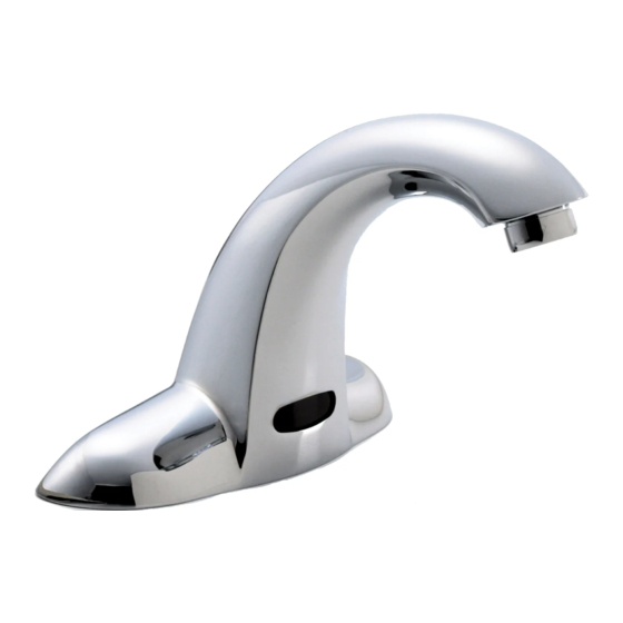
063211A
Spout Assembly
NOTE: Control Box #0 and #1 are designed for routine
171°F (77°C) disinfection cycles up to 30 minutes.
Control Box #8 is not recommended for high temperature
disinfection cycles as the thermostatic mixing valve limits
the higher temperature flow output.
NOTE: For optimum performance of this product, we
recommend a system pressure between 20 and 80 PSI
static. This product will operate up to a maximum of 125
PSI static per ANSI and CSA requirements. However,
we do not recommend pressure above 80 PSI. Thermal
expansion or leaking pressure reducing valves may
require use of expansion tanks or relief valves to ensure
your system never exceeds its maximum intended
pressure setting.
061031A
Deck Gasket (3/pkg)
063257A
3/4" Solenoid Valve
w/adaptors for 3/8"
Compression
Page 1
Note: See page 3 for
parts breakdown on
recessed mount boxes.
OPTION LIST
060681A
Battery Holder
TRANSFORMERS
060704A
Transformer 110 to 24 VAC 20VA
up to 5 Electronic Valves
060771A
Transformer 110 to 24 VAC 40VA
up to 10 Electronic Valves
212294 Rev. B
Fig. 1
Advertisement
Table of Contents

Related Manuals for Delta 591T Series


Summary of Contents for Delta 591T Series
- Page 1 591T__ 2 __ __ Write purchase model number here for future reference Note: See page 3 for 060638A Vandal Resistant Laminar Outlet parts breakdown on with Antimicrobial by Agion ® 063211A 1.5 GPM (5.7 L/min) Spout Assembly recessed mount boxes. 060640A Vandal Resistant Flow Control Aerator and Wrench...
-
Page 2: Installation And Set Up Instructions
Installation should be in accordance with local plumbing and electrical codes. FLUSH ALL PIPES THOROUGHLY BEFORE INSTALLATION. INSTALLATION AND SET UP INSTRUCTIONS FOR SURFACE MOUNT HOUSING: CONTROL BOX #0 Fig. 2 STEP 1. FAUCET INSTALLATION 13" (331 mm) Max. Connect 20” braided hose to spout inlet. Clean deck/sink surface where faucet will be mounted. -
Page 3: Step 2. Faucet Installation
Installation should be in accordance with local plumbing and electrical codes. FLUSH ALL PIPES THOROUGHLY BEFORE INSTALLATION. INSTALLATION AND SET UP INSTRUCTIONS FOR RECESS MOUNT HOUSING: CONTROL BOXES #1 & 8 STEP 1. ROUGH IN Note: Wires connecting between box(es) and from transformer must be protected from abrasion, and being pulled at connections. They also may have to be fished through at a later stage of construction. - Page 4 INSTALLATION AND SET UP INSTRUCTIONS FOR RECESS MOUNT HOUSING: CONTROL BOXES #1 & 8 STEP 3. CONNECT WATER SUPPLY Fig. 8 Install sink and connect drainage to rough in. See applicable Fig. 6 or Fig. 7. Please note that the connec- tion and fittings are supplied by the installer to connect 1/2”...
-
Page 5: Step 8. Making Adjustments
INSTALLATION AND SET UP INSTRUCTIONS FOR RECESS MOUNT HOUSING: CONTROL BOXES #1 & 8 STEP 7. TEST FOR OPERATION Test for operation. If unit does not work properly, see Troubleshooting Guide on page 7. STEP 8. MAKING ADJUSTMENTS If adjustments are required. Note factory defaults for program shown in Quick Reference Chart. Otherwise, replace the driver board housing cover as the electronic product is ready for use. -
Page 6: Battery Strength Indicator
● bAd - Replace Batteries (buzzer will annunciate and LED will blink if activated - if these features are turned on). Faucet will disable itself if batteries are not replaced. If you have any questions about the installation of this product or need help troubleshooting this product, please call Delta Commercial Technical Services at 1-800-387-8277 (Canada) or 1-877-509-2680 (U.S.A.). -
Page 7: Care Instructions
CARE INSTRUCTIONS This Delta Commercial faucet is designed and engineered in accordance with the highest quality and performance standards. With proper care, it will give years of trouble free service. Care should be given to the cleaning of this product. Although the chrome finish is extremely durable, it can be DAMAGED by ACIDIC CLEANERS (i.e. - Page 8 ® All parts of Delta® HDF® and TECK® faucets are warranted to the original commercial purchaser to be free from defects in material, nish and workmanship for a period of ve (5) years unless otherwise speci cally stated in the catalogue and price book. This warranty is made to the original commercial purchaser and shall be e ective from date of purchase as shown on the purchaser’s receipt.
Need help?
Do you have a question about the 591T Series and is the answer not in the manual?
Questions and answers