Advertisement
Make sure no obstacles are in the desk's path.
Make sure the desktop is not touching any walls.
Make sure all cords are appropriate length to accommodate the
change in height.
Keep children away from electric height-adjustable desks, control units and handsets. There is a risk of injury and electric
•
shock.
Keep all electrical components away from liquids.
•
Do not sit or stand on the desk frame. Do not crawl or lie under the desk frame.
•
Do not open any of the components - legs, control box, or switch. There is a danger of electric shock.
•
This product is designed with a duty cycle of 10%. (2 min. on, 18 min. off).
•
This height adjustable desk has electric motors and is designed for use in dry work areas only.
•
The desk height is adjustable so that it can be positioned at the most ergonomically suitable height.
•
Any other use is at user's risk.
•
Under no circumstances does the manufacturer accept warranty claims or liability claims for damage caused from
•
improper use or handling of the desk frame.
USE / LIABILITY
Pinch Point! Keep hands and fingers clear.
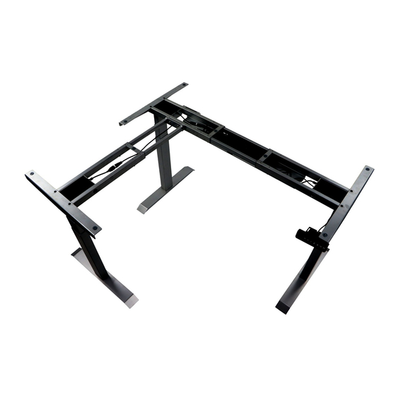
PARTS
WARNING
Page 1 from 4
Advertisement
Table of Contents

Related Manuals for STEMA UT04-3T-90A


Summary of Contents for STEMA UT04-3T-90A
- Page 1 Assembly instruction Make sure no obstacles are in the desk’s path. WARNING Make sure the desktop is not touching any walls. Make sure all cords are appropriate length to accommodate the Pinch Point! Keep hands and fingers clear. change in height. Keep children away from electric height-adjustable desks, control units and handsets.
- Page 2 Required tools Components ASSEMBLY INSTRUCTION Page 2 from 4...
- Page 3 Page 3 from 4...
- Page 4 Attach the desk base assembly to the underside of the desktop using six M5*16 screws (for desktops more like 20 mm thickness): 2 per side bracket – 6 in total, – 1 per crossbar end - 3 in total. – Attach the control box (6) to the middle of the crossbar, adjust the frame length with top, then covered the cable tray with crossbar ends.
Need help?
Do you have a question about the UT04-3T-90A and is the answer not in the manual?
Questions and answers