Table of Contents
Advertisement
This is a safety alert symbol and should never be ignored. When you see this symbol on labels or in
manuals, be alert to the potential for personal injury or death.
WARNING
Improper installation, adjustment, alteration, service
or maintenance can cause property damage, personal
injury or loss of life. Installation and service must be
performed by a licensed professional HVAC installer or
equivalent, service agency, or the gas supplier.
IMPORTANT
The Clean Air Act of 1990 bans the intentional venting
of refrigerant (CFCs, HCFCs and HFCs) as of July
1, 1992. Approved methods of recovery, recycling or
reclaiming must be followed. Fines and/or incarceration
may be levied for noncompliance.
507789-01
INSTALLATION INSTRUCTIONS
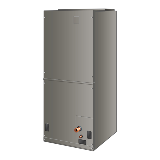
BCE5V Series Air Handler
This manual must be left with the homeowner for future reference.
Save these instructions for future reference
Table of Contents
Shipping and Packing List ...........................................3
General ........................................................................3
Requirements ..............................................................3
Use of Air Handler During Construction.......................4
Installation Clearances ................................................4
Installation ...................................................................4
Condensate Drain........................................................7
Duct System and Filters .............................................9
Brazing Refrigerant Lines ............................................9
Sealing the Unit .........................................................11
Electrical Connections ...............................................12
BDC3 Blower Control ................................................16
Adjusting the Blower Speed ......................................16
Blower Performance ..................................................17
Checkout Procedures ................................................21
Professional Maintenance .........................................22
Homeowner Maintenance..........................................22
Repairing or Replacing Cabinet Insulation ................22
As with any mechanical equipment, contact with sharp
sheet metal edges can result in personal injury. Take
care while handling this equipment and wear gloves
and protective clothing.
A Lennox International, Inc. Company
*P507789-01*
Issue 2007
CAUTION
Manufactured By
Allied Air Enterprises LLC
215 Metropolitan Drive
West Columbia, SC 29170
(P) 507789-01
Page 1 of 24
Advertisement
Table of Contents

Related Manuals for Armstrong Air BCE5V Series


Summary of Contents for Armstrong Air BCE5V Series
-
Page 1: Table Of Contents
INSTALLATION INSTRUCTIONS BCE5V Series Air Handler This manual must be left with the homeowner for future reference. This is a safety alert symbol and should never be ignored. When you see this symbol on labels or in manuals, be alert to the potential for personal injury or death. -
Page 2: Bce5V Unit Dimensions - Upflow - Inches (Mm)
BCE5V Unit Dimensions – Upflow – Inches (mm) 1 (25) DETAIL OF PIPING PLATE 4-3/4 3/4 (19) (121) SUCTION LINE SUPPLY AIR LIQUID OPENING CONDENSATE LINE 14-1/2 DRAINS (2) (368) 2-3/8 (Horizontal) (60) 1 (25) 1 (25) CONDENSATE DRAINS (2) 4-3/8 (Upflow and (111) -
Page 3: Shipping And Packing List
Code, ANSI/NFPA No. 70 (latest edition) in the United General States, and any state laws, and local ordinances (including plumbing or waste water codes). The BCE5V series air handler with Omniguard coil Local authorities having jurisdiction should be consulted is designed for indoor installation only. As shipped, the before installation is made. -
Page 4: Use Of Air Handler During Construction
• The air handler evaporator coil, supply fan assembly and duct system must be thoroughly cleaned following IMPORTANT final construction clean-up. Excessive condensation may occur if the unit is installed • All air handler operating conditions must be verified in a warm, humid place. When the unit is installed in an according to these installation instructions. - Page 5 finished enclosure. Knockouts are provided for electrical NOTE: When the unit is installed in horizontal applications, wiring entrance. a secondary drain pan is recommended. Refer to local codes. For ease in installation, it is best to make any necessary NOTE: This unit may be installed in left-hand or right-hand coil configuration changes before setting air handler in place.
- Page 6 Left-Hand Air Discharge Rotate drip shield 180° front-to-back. For horizontal left-hand air discharge, the following field Remove plastic plug from left hole on coil front end modifications are required. seal and reinstall plug in back hole. Reinstall drip shield screw in front coil end seal. Drip shield should drain downward into horizontal drain pan inside coil.
-
Page 7: Condensate Drain
Downflow Application If downflow application is required, separately order a THIS CORNER SHOULD BE 5/8" (+/- 1/8") HIGHER THAN DRAIN CORNER downflow conversion kit and install per kit instructions. See Table 1 for kit information. Also use metal or class I supply and return air plenums. - Page 8 OVERFLOW DRAIN LINE ABOVE ALWAYS RUN AN OVERFLOW DRAIN LINE. IF NOT POSSIBLE TO FINISHED ROUTE OVERFLOW DRAIN LINE, INSTALL LOW VOLTAGE SPACE? VENT MUST EXTEND OVERFLOW SWITCH KIT. WIRE SHUT DOWN ABOVE HEIGHT OF COMPRESSOR PER INSTRUCTIONS. COIL DRAIN PAN BY TWO INCHES (51MM) VENT PART #...
-
Page 9: Duct System And Filters
Duct System and Filters Cabinet and Duct Flange CABINET DOOR FLANGE Duct System 1−1/2 The air handler is provided with flanges for the connection (38) of the supply plenum. Supply and return duct system must be adequately sized DUCT to meet the system’s air requirements and static pressure FLANGE capabilities. - Page 10 WALLS, DUCT SYSTEM, FLOOR JOISTS, OR OTHER PIPING. REMOVE RUBBER PLUG FROM BOTH LIQUID AND SUCTION LINES NOTE - BCE5V SERIES UNITS USE NITROGEN OR DRY AIR AS A HOLDING CHARGE. IF THERE IS NO PRESSURE PIPING WHEN THE RUBBER PLUGS ARE REMOVED, CHECK THE PLATE COIL FOR LEAKS BEFORE INSTALLING.
-
Page 11: Sealing The Unit
Sealing the Unit WARNING Seal the unit so that warm air is not allowed into the cabinet. To prevent the build-up of high levels of Warm air introduces moisture, which results in water blow- nitrogen when purging, it must be done in a off problems. -
Page 12: Electrical Connections
• Electrical wiring, disconnect means and over-current Electrical Connections protection are to be supplied by the installer. Refer to the air handler rating plate for maximum over- current protection, minimum circuit ampacity, as well WARNING as operating voltage. Select the proper supply circuit conductors in accordance with tables 310-16 and 310- Electric shock hazard! - Disconnect all power 17 in the National Electric Code, ANSI/NFPA No. - Page 13 208 Volt Conversion Disconnect all power supplies. 1. Disconnect all power supplies. Remove the air handler access panel. Remove the air handler access panel. Route the field supply wires to the air handler electrical connection box. Using the wiring diagram located on the unit access panel as a reference, move the 2 connected black Use UL-listed wire nuts to connect the field supply transformer leads from the 240 volt terminal on the...
- Page 14 4KW & 5KW Figure 14. Typical Wiring Diagram – BCE5V Air Handler with Electric Heat – (Variable-Speed Motor) Page 14 of 24 Issue 2007 507789-01...
- Page 15 WARNING USE COPPER CONDUCTORS ONLY Figure 15. Low Voltage Connections (Variable-Speed Motor) 507789-01 Issue 2007 Page 15 of 24...
-
Page 16: Bdc3 Blower Control
NORM OPERATIONAL SELECTOR PINS Table 4 lists the recommended factory blower speed tap (AFFECTS BOTH TEST HEATING AND selections for BCE5V series units. These settings are ADJUST HEAT COOL DELAY CFM RUN COOLING MODES) for nominal tonnage match-ups with the BCE5V. When... -
Page 17: Blower Performance
Comfort and -) with their respective CFM volumes. Notice that for Sync thermostat and the BCE5V series unit. ® the 1.5 ton unit, for example, that the normal adjustment setting for heat speed position #4 is 1050 CFM. The +... - Page 18 BCE5V24 Blower Performance 0 through 0.80 in. w.g. External Static Pressure Range Jumper Speed Positions “HEAT” Speed First Stage “COOL” Speed Second Stage “COOL” Speed ADJUST Jumper Setting 1120 1120 NORM 1050 1050 – NOTES - The effect of static pressure, filter and electric heater resistance is included in the air volumes listed. First stage cooling air volume is 70% of COOL speed setting.
- Page 19 BCE5V48 Blower Performance 0 through 0.80 in. w.g. External Static Pressure Range Jumper Speed Positions “HEAT” Speed First Stage “COOL” Speed Second Stage “COOL” Speed ADJUST Jumper Setting 1375 1600 1820 2185 1125 1285 1620 1375 1600 1820 2185 NORM 1260 1455 1655...
- Page 20 Operating Sequence System Demand System Response Thermostat Demand Relative Humidity Air Handler System Step Comp Comments Condition Status (COOL) NO CALL FOR DEHUMIDIFICATION Normal Accetpable Compressor and indoor Operation - Y1 air handler follow Normal thermostat demand Accetpable High 100% Operation - Y2 Room Thermostat Calls for First-Stage Cooling BASIC MODE (only active on a Y1 thermostat demand)
-
Page 21: Checkout Procedures
Heat Jumper The HEAT jumper is used to determine CFM during electric heat operation only. These jumper selections are activated 7 1/2 MIN 100% only when W1 is energized. 82% CFM 1/2 MIN 1/2 MIN 50% CFM 50% CFM COOLING DEMAND Delay Jumper The DELAY jumper is used to set the specific motor fan operation during cooling mode. -
Page 22: Professional Maintenance
Check the air flow from a register to confirm that the If water should start coming from the secondary drain system is moving cooled air. line, a problem exists which should be investigated and corrected. Contact a qualified service technician. Set the thermostat 5ºF higher than the indoor temperature. - Page 23 Installing Contractor’s Name_______________________ Installing Date_______________________________ Installing Contractor’s Phone_______________________ Air Handler Model #___________________________ Job Address____________________________________ Thermostat Line Voltage SUPPLY Disconnect Switch Integrated Control Temperature Duct Blower Motor Amps System Electric Heat Amps Duct Static RETURN Filter Drain Line DUCT SYSTEM TOTAL EXTERNAL STATIC (dry coil) dry coil wet coil SUPPLY AIR DUCT...
- Page 24 Installing Contractor’s Name_______________________ Installing Date_______________________________ Installing Contractor’s Phone_______________________ Air Handler Model #___________________________ Job Address____________________________________ Line Voltage Disconnect Switch Thermostat Integrated Control Duct System Duct System Filter RETURN SUPPLY Electric Heat Amps Blower motor Amps Drain Line Duct Static Temperature DUCT SYSTEM TOTAL EXTERNAL STATIC (dry coil) dry coil wet coil...
Need help?
Do you have a question about the BCE5V Series and is the answer not in the manual?
Questions and answers