Table of Contents
Advertisement
This is a safety alert symbol and should never be ignored. When you see this symbol on labels or in
manuals, be alert to the potential for personal injury or death.
Unit Dimensions ..........................................................2
Model Number Identification ........................................4
General Information ....................................................5
Shipping and Packing List ..........................................5
Installation Clearances ...............................................5
Requirements .............................................................5
Installation ...................................................................6
Brazing Connections ................................................10
Condensate Drain .....................................................12
Inspecting and Replacing Filters ..............................13
NOTE: Special procedures are required for cleaning the all-aluminum coil in this unit. See Page 37 in this instruction
for information.
IMPORTANT INFORMATION FOR INSTALLER
CHECK FOR AND REMOVE THE FOLLOWING ITEMS BEFORE OPERATING UNIT.
A
BLOWER HOUSING SUPPORT PAD
FOR PROPER OPERATION THE ELECTRIC HEAT (IF APPLICABLE) MUST BE
CONFIGURED (SET-UP) THROUGH THE AIR HANDLER CONTROL (AHC)
H
Manufactured By
Allied Air Enterprises LLC
A Lennox International, Inc. Company
215 Metropolitan Drive
West Columbia, SC 29170
507746-01
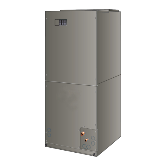
INSTALLATION INSTRUCTIONS
BCE7S Series Air Handler
This manual must be left with the homeowner for future reference.
Table of Contents
B
HORIZONTAL DRAIN PAN (SEE
UPFLOW APPLICATIONS ON PAGE
6 AND DOWNFLOW APPLICATIONS
ON PAGE 8 )
IMPORTANT: WHEN ELECTRIC HEAT IS INSTALLED, THE
AIR HANDLER CONTROL MUST BE MANUALLY
CONFIGURED. SEE JUMPERS AND LINKS GUIDE ON
PAGE 19.
CONFIGURE ELECTRIC HEAT
ELECTRIC HEAT SECTIONS MUST BE
H
CONFIGURED.
PROCEDURE IN FIGURE 22 ON PAGE 31.
Save these instructions for future reference
Sealing the Unit ........................................................13
Field Control Wiring ..................................................13
Unit Operating Sequences .......................................27
Operation ...................................................................35
Repairing or Replacing Cabinet Insulation ................36
Homeowner Maintenance..........................................36
Professional Maintenance .........................................37
Checkout Procedures ................................................37
C
REFRIGERANT LINE PLUGS (SEE
BRAZING CONNECTION ON PAGE 10)
IF
INSTALLED,
SEE
ECB27
Issue 1821
*P507746-01*
(P) 507746-01
Page 1 of 39
Advertisement
Table of Contents

Related Manuals for Armstrong Air BCE7S Series


Summary of Contents for Armstrong Air BCE7S Series
-
Page 1: Table Of Contents
INSTALLATION INSTRUCTIONS BCE7S Series Air Handler This manual must be left with the homeowner for future reference. This is a safety alert symbol and should never be ignored. When you see this symbol on labels or in manuals, be alert to the potential for personal injury or death. -
Page 2: Unit Dimensions
Unit Dimensions Upflow and Downflow Unit Dimensions - Inches (mm) PIPING PLATE DETAIL 3/4 (19) (FOR UP-FLOW AND DOWN-FLOW POSITIONS) 5/8 (16) SUPPLY AIR OPENING 4 3/8 (111) 1 1/8 (29) SUCTION LINE CONDENSATE DRAINS 5/8 (16) 5/8 (16) (2) (HORIZONTAL) 3/4 (19) Return Air Opening... - Page 3 Horizontal Left- and Right-Hand Discharge Unit Dimensions – Inches (mm) 5 3/8 FILTER (137) (51) Horizontal Position LIQUID LINE (Right Hand Air SUCTION CONDENSATE Discharge) LINE DRAINS (2) (UP-FLOW Coil BLOWER 1 1/8 DOWN-FLOW) (29) CONDENSATE 4 3/8 DRAINS (2) (HORIZONTAL) (111) FOR DIMENSIONS “A”...
-
Page 4: Model Number Identification
Model Number Identification B C E 7 S 3 6 M A 4 X - 5 0 Unit Type Minor Revision Number BC = Air Handler Refrigerant Metering Device Enhanced 4X = R410A with expansion valve Voltage Series A = 208/230V-60hz-1ph Blower Motor Configuration Communicating enabled with... -
Page 5: General Information
General Information IMPORTANT This indoor unit with all-aluminum coil is designed for This unit must be matched with an indoor coil as installation with optional field-installed electric heat and specified in the AHRI Database. Coils previously a matched outdoor unit that is charged with HFC-410A charged with HCFC-22 must be flushed. -
Page 6: Installation
Installation These units are factory-configured for upflow and horizontal right-hand discharge installation. For downflow or horizontal left-hand discharge, certain field modifications are required. HORIZONTAL DRAIN PAN (MUST BE REMOVED) Disassemble/Reassemble Air Handler Units UP-FLOW / DOWN-FLOW The air handler units consists of two factory-assembled DRAIN PAN sections. - Page 7 UP-FLOW / DOWN-FLOW HORIZONTAL DRIP SHIELD (BCE7S60 MODELS) DRAIN PAN IMPORTANT When removing the coil, there is possible danger of equipment damage and personal injury. Be careful when removing the coil assembly from a unit installed in right- or left-hand applications. The coil may tip into the drain pan once it is clear of the cabinet.
- Page 8 Use the following procedures to configure the unit for rail then replace screws. Also, seal around the exiting horizontal left-hand discharge operations: drain pipe, liquid and suction lines to prevent infiltration of humid air. 1. Pull the coil assembly from unit. Pull off the horizontal drain pan.
- Page 9 Replace the coil assembly and blower if you have Units Length Width removed it. Replace the coil access panel. Not Required Not Required Set the unit so that it is level. Using sheet metal screws, 15-7/8ʺ 4-11/16ʺ connect the return and supply air plenums as required. 36, 42 17-7/8ʺ...
-
Page 10: Brazing Connections
Brazing Connections IMPORTANT To prevent the build-up of high levels of nitrogen when purging, it must be done in a well-ventilated area. WARNING Purge low-pressure nitrogen (1 to 2 psig) through Polyolester (POE) oils used with HFC-410A refrigerant the refrigerant piping during brazing. This will help to absorb moisture very quickly. - Page 11 REMOVE ACCESS PANEL REMOVE RUBBER PLUG FROM BOTH LIQUID AND SUCTION LINES NOTE — BCE7S SERIES UNITS USE NITROGEN OR DRY AIR AS A HOLDING CHARGE. IF THERE IS NO PRESSURE WHEN THE RUBBER PLUGS ARE REMOVED, CHECK THE COIL FOR LEAKS BEFORE INSTALLING.
-
Page 12: Condensate Drain
12 for main and overflow drain locations based on coil Condensate Drain orientation. UP-FLOW OR LEFT-HAND AIR RIGHT-HAND AIR DOWN-FLOW DISCHARGE DISCHARGE IMPORTANT After removal of drain pan plug(s), check drain hole(s) to verify that drain opening is fully open and free of any debris. -
Page 13: Inspecting And Replacing Filters
• It is recommended that the overflow drain line be Seal the unit so that warm air is not allowed into the cabinet. vented and a trap installed. Refer to local codes. Warm air introduces moisture, which results in water blow- off problems. - Page 14 Figure 14. BCE7S Air Handler Unit Typical Wiring Diagram Page 14 of 39 Issue 1821 507746-01...
- Page 15 BCE7S COMFORT SYNC™ AIR HANDLER CONTROL COMES FROM FACTORY WITH A METAL JUMPERS BETWEEN W1 TO W2 AND W2 TO W3. SEE FIGURE 22 FOR HEAT SECTION CONFIGURATION. CONDITIONER UNIT (TWO-STAGE) AIR HANDLER CONTROL IMPORTANT — CARE WHEN CUTTING ON-BOARD LINKS TO PREVENT DAMAGE TO CONTROL.
- Page 16 OUTDOOR IMPORTANT — CARE WHEN CUTTING SENSOR ON-BOARD LINKS TO PREVENT DAMAGE TO (X2658) CONTROL. SEE FIGURE 19, BCE7S JUMPER AND LINK GUIDE, FOR FURTHER DETAILS. EDA UNIT RELAY BCE7S Y1-Y2 COMFORT SYNC CUT ON-BOARD LINK Y1-Y2 FOR TWO- 2-STAGE THERMOSTAT STAGE A/C COMPR...
- Page 17 Wiring Connections Control Connections and Wiring Requirements 1. Install line voltage power supply to unit from a properly This section provides information on communicating and installed circuit breaker. non-communicating control connections and wire run lengths. Ground unit at unit disconnect switch or to an earth ground.
- Page 18 Function Indoor Control Non-Communicating Room Thermostat Indoor Communicating Outdoor Non- Full Communication Terminal Label (Indoor and Outdoor -24 volts) Communicating (Indoor & Outdoor) Indicates a first-stage heating demand. This W1 (Input) input is an anticipator for the thermostat. Indicates a second-stage h eating demand. W2 (Input) W1 input must be active to recognize second-stage heat demand.
- Page 19 2-STG COMPRESSOR 1-STG COMPRESSOR JUMPER & LINK GUIDE CUT LINK DO NOT CUT COOLING MODE HEATING MODE BLOWER SPEED BLOWER SPEED (COOLING & HP MODE) (ELECTRIC HT MODE) A/C UNIT HEAT PUMP UNIT HIGH HIGH DO NOT CUT CUT LINK SPEED SPEED 1 2 3 4...
-
Page 20: Air Handler Control Button, Display And Jumpers
• If jumper is installed in AUTO Humidification Air Handler Control Button, Display and position, H terminal is energized whenever indoor Jumpers blower is running. Blower Only CFM — Used to select Indoor blower Use Figure 19 as reference for jumper settings. If any of the CFM for continuous operation. - Page 21 Delay Profile 2 A. When cool demand is initiated, motor ramps up to 82%. Cooling – Air Conditioner and Heat Pump B. Motor runs at 82% for approximately 7.5 minutes and then ramp up to 100% (unless the demand has been 100% CFM 100% CFM satisfied) and motor runs at 100% until demand is...
- Page 22 NOTE — AHC MUST BE IN IDLE MODE) Single Character LED Display Action Solid Push and hold button until solid appears, release button. Display will blink. Blinking Push and hold button until required symbol displays. CONFIGURING ELECTRIC HEAT SECTIONS Release push button - control will cycle the indoor blower motor on to the selected heat speed and stage the electric heat relays on and o to automatically detect number of electric heat Solid sections.
- Page 23 Alert Priority Alert How to Clear Code Equipment is unable to communicate. This may indicate the existence of other alarms / The air-handler has lost codes. In most cases errors are related to electrical noise. Make sure high voltage power E105 Critical communication with the rest of...
- Page 24 Alert Priority Alert How to Clear Code The O relay on the air-handler has failed. Either the pilot relay O relay failed. Pilot relay contacts did not close or the relay coil did not energize. Replace E345 Critical contacts did not close or the control.
- Page 25 Target CFM Tables BCE7S24M Blower Performance 0 through 0.80 in. w.g. External Static Pressure Range Jumper Speed Positions "Adjust" "HEAT" Speed "COOL" Speed Jumper Setting 1050 1050 NORM NOTES: • The effect of static pressure, filter and electric heater resistance is included in the air volumes listed. •...
- Page 26 BCE7S42M Blower Performance 0 through 0.80 in. w.g. External Static Pressure Range Jumper Speed Positions "Adjust" "HEAT" Speed "COOL" Speed Jumper Setting 1100 1320 1540 1760 1100 1320 1540 1760 NORM 1000 1200 1400 1600 1000 1200 1400 1600 1080 1260 1440 1080...
-
Page 27: Unit Operating Sequences
Unit Operating Sequences This section details unit operating sequence for non-communicating systems. NOTE: For communicating systems, see the Comfort Sync thermostat installation instruction. Operating Sequence System Demand System Response Thermostat Demand Relative Humidity System Handler Step Comp Comments Condition Status (COOL) NO CALL FOR DEHUMIDIFICATION Compressor and indoor air handler... - Page 28 Operating Sequence System Demand System Response Thermostat Demand Relative Humidity System Handler Step Comp Comments Condition Status (COOL) NO CALL FOR DEHUMIDIFICATION Normal Operation Acceptable 24 VAC - Y1 Compressor and indoor air handler follow thermostat demand. Normal Operation Acceptable 24 VAC High 100%...
- Page 29 Configuring Unit This section identifies the requirements for configuring the air handler unit for unit size and heat mode selection. Air Handler Control Checkout Power-up - Unit Size Code (Number or letter) displayed represents air handler model size and ≡ capacity.
- Page 30 Configuring Unit Size Codes (Model Number) ≡ Power-up — Unit Size Code (number or letter) displayed represents air handler model and capacity. If three horizontal bars are displayed, then Air Handler Control (AHC) does not recognize unit size code. Air handler control in IDLE mode (No heating, cooling or indoor fan operation) To enter unit size code configuration mode;...
- Page 31 Configuring/Detecting Electric Heat Sections IMPORTANT — All electric heat installations require the Air Handler Control (AHC) to be manually configured to detect number of heat sections. NOTE — All field replacement air handler controls must be configured to detect electric heat sections. NOTE - USE FIGURE 19 AS A REFERENCE FOR SETTING JUMPER CONFIGURATIONS ON THE AIR HANDLER CONTROL.
- Page 32 Heat Pump Operation (Heating and Cooling) Air Handler Control (AHC) Indoor Blower Mode Speed and Profile settings Set Cooling Mode Blower Speed jumper pin . (Low and high indoor blower CFM settings are identical for CUT ON-BOARD LINK Y1-Y2 cooling and heat pump) 2-STAGE Y1-Y2 FOR COMPR...
- Page 33 Cooling Operation Air Handler Control (AHC) Indoor Blower Mode Speed and Profiles settings Set Cooling Mode Blower Speed jumper pin. Y1-Y2 Set Cooling Mode Blower Ramping jumper pin. CUT ON-BOARD LINK Y1-Y2 FOR 2-STAGE Set Blower Adjust Selection jumper pin. TWO-STAGE A/C COMPR Single or Two-Stage Unit...
- Page 34 Error Code / Recall Mode Air handler control in Idle Mode (No heating cooling or indoor fan operation) To enter Error Code Mode,, push and hold Turn room thermostat to OFF. button next to single character LED display until solid E symbol appears, release button.
-
Page 35: Operation
Indoor Blower Test Indoor Blower Test Mode Air handler control in Idle Mode (No heating cooling or indoor fan operation) To enter indoor blower test mode, push and hold button next to single character LED display until Turn room thermostat to —... -
Page 36: Repairing Or Replacing Cabinet Insulation
Heating (Heat Pump) If the insulation in need of repair is otherwise in good condition, the insulation should be cut in an X pattern, When the thermostat calls for heating, 24 volts is applied to peeled open, glued with an appropriate all-purpose glue the blower time-delay relay coil. -
Page 37: Professional Maintenance
• Replace disposable filters. Cleanable filters can be • Have ALL unused drain pan ports been properly cleaned by soaking in mild detergent and rinsing with plugged? cold water. • Has the condensate line been properly sized, run, • Install new/clean filters with the arrows on the side trapped, pitched, and tested? pointing in the direction of airflow. - Page 38 Installing Contractor's Name_______________________ Installing Date_______________________________ Installing Contractor's Phone_______________________ Air Handler Model #___________________________ Job Address____________________________________ Thermostat Line Voltage SUPPLY Disconnect Switch Integrated Control Temperature Duct Blower Motor Amps System Electric Heat Amps Duct Static RETURN Filter Drain Line DUCT SYSTEM TOTAL EXTERNAL STATIC (dry coil) dry coil wet coil SUPPLY AIR DUCT...
- Page 39 Installing Contractor's Name_______________________ Installing Date_______________________________ Installing Contractor's Phone_______________________ Air Handler Model #___________________________ Job Address____________________________________ Line Voltage Disconnect Switch Thermostat Integrated Control Duct System Duct System Filter RETURN SUPPLY Electric Heat Amps Blower motor Amps Drain Line Duct Static Temperature DUCT SYSTEM TOTAL EXTERNAL STATIC (dry coil) dry coil wet coil...
Need help?
Do you have a question about the BCE7S Series and is the answer not in the manual?
Questions and answers