Table of Contents
Advertisement
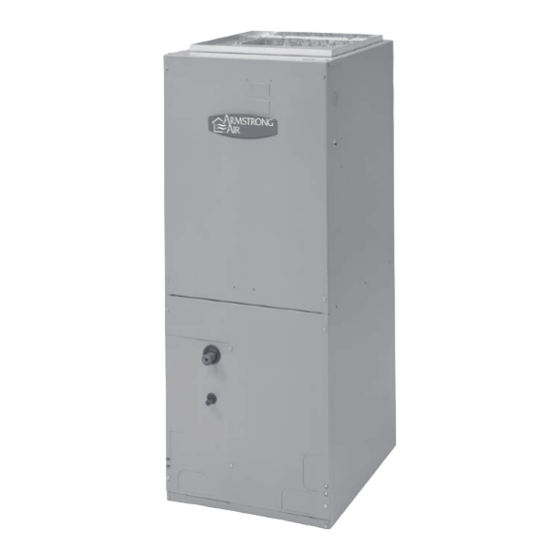
RBCS2/BCS2 Series Air Handler
Your safety and the safety of others are very important.
We have provided many important safety messages in this manual and on your appliance. Always read and obey all safety
messages.
All safety messages will tell you what the potential hazard is, tell you how to reduce the chance of injury, and tell you what
can happen if the instructions are not followed.
1
Installation Instructions
Table of Contents
AIR HANDLER SAFETY
This is the safety alert symbol.
This symbol alerts you to potential hazards that can kill or hurt you and
others.
All safety messages will follow the safety alert symbol and
either the word "DANGER" or "WARNING." These words mean:
1
2
2
2
2
3
4
5
6
6
6
7
7
8
You can be killed or seriously injured if
you don't immediately follow
instructions.
You can be killed or seriously injured if
you don't follow instructions.
659373-10
May, 2007
8
-
8
9
11
12
13
13
14
14
14
14
Advertisement
Table of Contents

Summary of Contents for Armstrong Air RBCS2 Series
-
Page 1: Table Of Contents
659373-10 May, 2007 RBCS2/BCS2 Series Air Handler Installation Instructions Table of Contents AIR HANDLER SAFETY Connect Refrigerant Lines INSTALLATION REQUIREMENTS Make Electrical Connections – Tools and Parts Models Without Factory Installed Electric Heat Make Electrical Connections – Outdoor System Requirements Models With Factory Installed Electric Heat Location Requirements Wiring Diagram... -
Page 2: Installation Requirements
INSTALLATION REQUIREMENTS These instructions are intended as a general guide only and do Adjustable wrench • not supersede any national or local codes in any way. Tape Measure • Compliance with all local, state, or national codes pertaining to this type of equipment should be determined prior to installation. Hammer •... -
Page 3: Installation Configurations
For ease in installation, it is best to make any necessary coil If installed in an unconditioned space, sealant should be • configuration changes before setting air handler in place. See applied around the electrical wires, refrigerant tubing, “Installation Configuration Options.” and condensate lines where they enter the cabinet. -
Page 4: Drain Pan Connections
Requires drain pan location change A. Drain connections Drain Pan Connections Horizontal Installations can be either “Right” or “Left.” For horizontal right installations, a drain pan location change is required. Use drain connections “A” below. Installation Configuration Options Horizontal Right Requires drain pan location change Shading indicates proper line connections Upflow... -
Page 5: Electrical Requirements
Before Conversion For models 2.5 thru 5 ton the bracket attached to NOTE: the top plate will need to be switched to the opposite side of the coil. This is to prevent blowoff in the horizontal position when the airflow is changed from left hand to right hand. -
Page 6: Ductwork Requirements
These air handlers are completely factory assembled, and all components are performance tested. Each unit consists of a NOTE : Use copper conductors only. blower assembly, refrigerant coil, and controls, in an insulated galvanized steel factory finished enclosure. Knockouts are All field wiring must be done in accordance with National •... -
Page 7: Install Condensate Drain
secondary drain line to a place where the occupant would notice if water started coming from the secondary pan. Install a 3” trap in both the primary and secondary drain lines as close to the unit as practical. Make sure the top of the trap is below the connection to the drain pan to allow complete drainage of the pan. -
Page 8: Verify Orifice Size
connection must be run, full size, to a location outside the closet. Connect Refrigerant Lines Refrigerant lines must be connected by a licensed, EPA certified refrigerant technician in accordance with established procedures. Verify Orifice Size IMPORTANT: Connecting refrigerant lines must be clean, dehydrated, •... -
Page 9: Make Electrical Connections - Models With Factory Installed Electric Heat
Make Electrical Connections – Models With Factory-Installed Electric Heat Determine the number of circuits needed to supply the heater with electrical power (1, 2, or 3 circuits). See the air handler Accessory Kit label for number of circuits and ratings. Disconnect all power supplies. - Page 10 Line Voltage Connections Thermostat Air Handler Thermostat Air Handler Condensing unit Cooling Only Application Condensing Unit Thermostat Air Handler Cooling Application with Electric Heat Thermostat Air Handler Heat Pump Heating Only Application Connect common ( C ) wire only if required. See Thermostat Installation Instructions.
-
Page 11: Wiring Diagram
Wiring Diagram – Electric Heat and Blower... -
Page 12: Complete Installation
Complete Installation of cooling capacity (or 350 – 450 CFM per 12,000 BTU/HR) based on the rating of the outdoor unit. • The cooling blower speed is factory configured to NOTE: Refer to outdoor unit installation instructions for system provide correct airflow for an outdoor unit that matches start-up instructions and refrigerant charging instructions. -
Page 13: Blower Performance
Blower Performance Chart CFM @ESP. -in. W.C. Handler Model Blower Speed 0.10 0.20 0.30 0.40 0.50 Low* (Red) Med (Blue) High (Black) 1036 Low (Red) Med* (Blue) High (Black) 1036 Low (Red) Med* (Blue) 1059 1043 1014 High (Black) 1290 1271 1213 1153... -
Page 14: Air Handler Maintenance
AIR HANDLER MAINTENANCE Replace disposable filters. Cleanable filters can be • At the beginning of each heating season the unit should be cleaned by soaking in mild detergent and rinsing with serviced by a qualified installer or servicing agency. cold water. IMPORTANT: Do not operate system without a filter. -
Page 15: Warranty
Air Handler Limited Warranty General Five Year Parts Warranty: This equipment will perform at installation according to its specifications when installed, operated, repaired and serviced in strict accordance with the installation and maintenance instructions and using authorized service parts. This warranty applies only to equipment installed within the United States and Canada.


Need help?
Do you have a question about the RBCS2 Series and is the answer not in the manual?
Questions and answers