Table of Contents
Advertisement
Quick Links
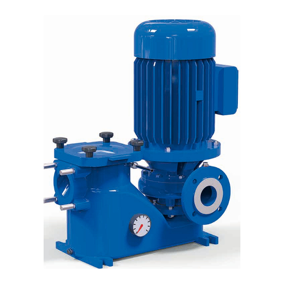
UNIBLOCK-WX
Operating manual
Close coupled centrifugal pump with integrated filter
Translation of the original
operating manual
Herborner Pumpentechnik GmbH & Co KG | Littau 3-5 | DE-35745 Herborn | Phone: +49 (0) 27 72 / 933-0
A - WX37 GB
Fax: +49 (0) 27 72 / 933-100 | E-mail: info@herborner-pumpen.de | www.herborner-pumpen.de
Advertisement
Table of Contents

Related Manuals for HERBORNER pumpentechnik UNIBLOCK-WX


Summary of Contents for HERBORNER pumpentechnik UNIBLOCK-WX
- Page 1 Translation of the original operating manual Herborner Pumpentechnik GmbH & Co KG | Littau 3-5 | DE-35745 Herborn | Phone: +49 (0) 27 72 / 933-0 A - WX37 GB Fax: +49 (0) 27 72 / 933-100 | E-mail: info@herborner-pumpen.de | www.herborner-pumpen.de...
- Page 2 Translation Copyright Deliveries to countries of the EEA require the operating The transfer and duplication of this document and utilisation manual to be translated in accordance with the language and communication of its content is prohibited, unless expli- spoken in the respective country. citly stated otherwise.
- Page 3 - Directive 2014/34/EU (for explosion protection version) Herborn, 20/04/2016 ..............Signature (Management) Original Herborner Pumpentechnik GmbH & Co KG | Littau 3-5 | DE-35745 Herborn | Phone: +49 (0) 27 72 / 933-0 Fax: +49 (0) 27 72 / 933-100 | E-mail: info@herborner-pumpen.de | www.herborner-pumpen.de...
-
Page 5: Table Of Contents
Table of contents Table of contents General Information ........6 Starting up ........... 27 Intended use ..........6 Maintenance/Cleaning ......28 Exploded view ..........8 Maintenance..........28 Wear parts ............. 8 Maintenance instructions during prolon- Technical data ..........9 ged periods of inactivity....... 29 1.4.1 Model designation ......... -
Page 6: General Information
The close coupled centrifugal pump with integrated filter contains abrasive components can UNIBLOCK-WX is particularly suitable for pumping and destroy the pump. filtering cutting coolant and other fluids containing coarse contaminants that are used in industrial plants. - Page 7 General information The explosion-proof centrifugal pumps satisfy the require- ments of electrical equipment for use in potentially explosive atmospheres in accordance with Directive 94/9/EC of the European Council dated 23 Mar- ch, 1994, for intended use in potentially explosive atmos- pheres for device group II category 2.
-
Page 8: Exploded View
General information Exploded view Individual components Filter casing Filter strainer Filter cover Star handle Pump casing Intermediate casing Impeller 320.1 Anti-friction bearing (non-drive side) 320.2 Anti-friction bearing (drive side) 400.1 Gasket 400.2 Gasket O-ring Labyrinth ring Mechanical seal Washer ventilation system pressure gauge Block motor Motor shaft... -
Page 9: Technical Data
General information Technical data 1.4.2 Impellers 1.4.1 Model designation Open multi-vane impellers are used for Example: pumped media with light contamination and 40-161/0222WX-EX-W1-S to provide operationally safe pumping. Nominal diameter of pressure flange DN [mm] Construction dimensions 1.4.3 Installation Impeller version Motor rating [kW] The pumps are delivered in vertical installation: E.g.: 022 = 2.2 kW... -
Page 10: Drive
General information Motor data Design IM B5 Danger! Motor connection Manufacturer-specific Air bubbles or accumulations of gas around the mechanical seal create a Protection type IP 55 potentially fatal explosive atmosphere. Speed 3000 (3600) rpm Provide a constant supply of pumped Frequency 50 (60) Hz media to the supply and pressure pipes... - Page 11 General information Density and viscosity of the pumped medium: Density: max. 1000 kg/m Kinematic viscosity: max. 1 mm /s (1 cST) Customer-specific solutions may differ from this standard data. Power correction: Reduce the power according to the specifications of the mo- tor manufacturer if motors are used at ambient temperatures >...
-
Page 12: Safety
Safety Safety The following signal words represent Notes/explanations This indicates an imminent danger. If it is not Danger! avoided, it will result in fatal injury or serious The following symbols represent personal injuries. Warning of a hazardous area This indicates a potentially dangerous situa- Warning! tion. -
Page 13: Integrated Safety Systems (Optional)
1/min Art.-Nr.: Drehrichtung beachten! Baujahr/Monat Caution! Herborner Pumpentechnik | GmbH & Co KG | Littau 3-5 | DE-35745 Herborn Impermissible heating will damage the three-phase motor. Figure 2b Name plate (explosion protection pump) Do not deactivate safety devices or change their mode of operation. -
Page 14: Connections On The Pump
Safety Connections on the pump Important! A trained person is understood to be someone who - has been instructed by a specialist about the tasks they are assigned and the possible dangers associated with improper conduct, - has received practical training, if necessary, and - has been informed about the necessary protective equip- ment and precautions. - Page 15 Safety The operating company has to obtain local operating licences and observe the associated conditions. In addition, they must comply with the local statutory pro- visions for - the safety of personnel (accident preven- tion regulations) - the safety of operating equipment (protec- tive equipment and maintenance) - product disposal (waste management legislation)
-
Page 16: General Hazard Warnings
General hazard warnings General Hazard Warnings Assembly, operation and maintenance personnel Assembly, operation and maintenance personnel are re- Dangers sponsible for the transportation, fitting, installation, operation, cleaning and trouble shooting of the pump. Warning! 1. Only trained and authorised persons are Maintenance and repair work can cau- allowed to install and operate the pump. -
Page 17: Shut-Off Procedures
General hazard warnings Shut-off procedures The following shut-off procedure must be complied with before conducting any maintenance, cleaning and/or repair work (by specialists only). Warning! Electric current can result in fatal injury. Disconnect the block motor (802) according to the 5 safety rules. When cleaning, close any electrical cabinets that are open to prevent dust or water from entering. -
Page 18: Transport
Transport Transport Packaging for transportation by HGV When the pump is transported by HGV, it is packed and Scope of delivery secured on a transport pallet. The detailed scope of delivery is in the order confirmation. 4.2.2 Intermediate storage Transport and packaging The freight packaging of the pump and the spare parts is sui- table for storage for a period of approximately three months. -
Page 19: Transportation With A Crane
Transport 4.3.2 Transportation with a crane - The crane must be able to support the full weight of the pump. - The operator must be authorised to ope- rate the crane. - Attach the pump to the crane at the spe- cified attachment points using appropriate separate lifting accessories (e.g. -
Page 20: Installation/Fitting
Installation/fitting Installation/Fitting To prevent vibrations being transmitted to the building and the pipeline system, it is advisable to install pipe compensators and vibration dampers. Installation Prepare for construction in accordance with the pump di- mensions. Caution! Injuries may be caused when installing Important! the pump. -
Page 21: Dimensions
Installation/fitting Dimensions øk Figure 5 Dimensions Model øk L max [kg] 25-110/0032 WX 25-110/0052 WX 25-110/0072 WX 25-181/0112 WX 25-181/0152 WX 25-181/0222 WX 32-131/0072 WX 32-131/0112 WX 32-131/0152 WX 32-161/0222 WX 32-191/0302 WX 32-191/0402 WX 40-161/0112 WX 40-161/0152 WX 40-161/0222 WX 40-161/0302 WX 40-191/0402 WX 50-161/0152 WX... -
Page 22: Technical Data
Installation/fitting Technical data The earth, neutral connection, residual current circuit brea- ker, etc. must - correspond to the directives of the local public utility com- 50Hz: 3000 rpm (400V) pany (PUC) and - function flawlessly according to the electrician's inspection. [kW] I [A] dB(A) -
Page 23: Direction Of Rotation Check
Installation/fitting Danger! Important! Risk of a potentially fatal explosion The motor circuit breaker should be during the installation phase. - regulated for nominal motor current during direct starting, Provide a constant supply of pumped - introduced into the delta link for star-delta starting and set media to the supply and pressure pipes to a maximum of 0.58-times the nominal current. -
Page 24: Changes In Direction Of Rotation
Installation/fitting 5.6.1 Changes in direction of rotation Motor voltage (motor name plate) 5.7.1 PTC thermistor connection Change the direction of rotation by swapping two phases of the feed cable in the control system. Discrepancies can arise due to the differences in motor manufacturer and size. -
Page 25: Frequency Converter Operation
Installation/fitting To the tripping unit Ensure measures are in place for complete ventilation during the laying procedure. Pressure pipe - lay frost-free, - secure and Important! - connect so they are stress-free. - Measurement voltage of max. 2.5 V DC! Pipe forces and moments must not affect the pump. -
Page 26: Commissioning
Commissioning Commissioning Danger! Inspect the pump before commissioning and carry out a Air bubbles or accumulations of gas functional check. When doing this, pay special attention to around the mechanical seal create a the following: potentially fatal explosive atmosphere. - Turn the motor shaft several times by Provide a constant supply of pumped hand. -
Page 27: Starting Up
Commissioning Important! Use a motor circuit breaker or appropriate motor protection with a tripping characteristic according to DIN VDE 0660. Do not exceed ten starting procedures per hour. This pre- vents a sharp increase in temperature in the motor and an excessive load on the pump, motor, seals and bearings. -
Page 28: Maintenance/Cleaning
Maintenance/cleaning Maintenance/Cleaning The pump is subject to vibrations during operation that can loosen the screw and clamp connections. Inspect the pump at The content and structure of this maintenance manual is regular intervals for any loose connections (recommendation based on DIN 31052 "maintenance". is every 6 months for single-shift operation). -
Page 29: Maintenance Instructions During Prolon- Ged Periods Of Inactivity
Maintenance/cleaning In addition, the following label can be found on the motor: Warning! When removing the pump from the pipe network, there is a risk of tipping which can result in serious injury. Secure the pump during transportation using appropriate separate lifting ac- cessories. -
Page 30: Seals
Maintenance/cleaning Seals Important! In general, a mechanical seal does not require any main- tenance. Anti-friction bearings that are used at a speed of Only replace the mechanical seal as a complete unit. This - 3000 (3600) rpm are to be re-lubricated or replaced, if ensures optimum shaft sealing. -
Page 31: Cleaning The Filter Strainer
Maintenance/cleaning Danger! Caution! The rotating impeller can cut or crush Escaping pumped media can cause people's hands and arms. burns to hands and arms. Observe section 3.5 “Shut-off proce- Depressurise the pump casing. dures”. Only then should you drain the pump. Disassembly of the filter strainer (002): Danger! 1. -
Page 32: Tightening Torques For Nuts And Bolts
Maintenance/cleaning Important! The points in section 6 ‘Commissioning’ must be fulfilled before recommissioning the pumps. Tightening torques for nuts and bolts Stainless Non-stainless Thread (A4) 10.9 [Nm] [Nm] [Nm] 18.5 23.0 32.0 37.0 46.0 64.0 57.0 80.0 110.0 135.0 195.0 275.0 230.0 385.0... -
Page 33: Disturbance/Cause/Trouble Shooting
Disturbance/cause/trouble shooting Disturbance/Cause/Trouble Disturbance Cause Trouble shooting Shooting The delivery of The pumped Dilute the pum- the pump is too medium is too ped medium The facts and information in this manual regarding "Di- low. dense. or change the sturbance, Cause and Trouble Shooting" are addressed to process. - Page 34 Disturbance/cause/trouble shooting Disturbance Cause Trouble shooting Disturbance Cause Trouble shooting Pump installed Connecting pipes Anti-friction bea- Replace anti- under tension. must be laid ring defective. friction bearing. stress-free. Electric motor Incorrect pump Check the direc- Cavitation Check supply for gets excessively direction of rota- tion of rotation blockages.
-
Page 35: Disassembly/Assembly
Disassembly/assembly Disassembly/Assembly Caution! The pump is made mainly of steel. Dispose of the pump, oils Escaping pumped medium can cause and any cleaning agents in accordance with applicable local burns to hands and arms and flood environmental protection regulations. the area. Dispose of cleaning tools and utensils like brushes, rags, Close the pressure and suction-side etc. - Page 36 Disassembly/assembly Pull the intermediate casing Loosen the nut (920). (113) over the motor shaft (819). Notice! A damaged fitting surface does not guarantee a precise seal. Remove the washer (554). Do not damage the seating for the O-ring. Remove all components of the mechanical seal (433) from the intermediate casing (113).
-
Page 37: Assembly
Disassembly/assembly Assembly Before starting to reassemble the pump, all of the dismantled parts must be Important! - checked for signs of damage and wear, Do not damage the counter ring of the mechanical seal on the - cleaned and thread and transition of the motor shaft or press it at an angle! - replaced with original spare parts if necessary. - Page 38 Disassembly/assembly Use assembly aids (accesso- Important! ries) (if available) to ensure Turn back jack screws beforehand. an optimal seating of the mechanical seal on the motor Place the gasket (400.1) bet- shaft (819). ween the pump casing (101) and the intermediate casing (113).
- Page 39 Disassembly/assembly Important! - Check that the impeller (230) can run freely by turning it! - Carry out the electrical connection of the block motor (see section 5.4 'Electrical connection')! • Observe the connection type (refer to the name plate on the motor) •...
Need help?
Do you have a question about the UNIBLOCK-WX and is the answer not in the manual?
Questions and answers