Table of Contents
Advertisement
Advertisement
Table of Contents

Related Manuals for HERBORNER pumpentechnik UNIBAD-X


Summary of Contents for HERBORNER pumpentechnik UNIBAD-X
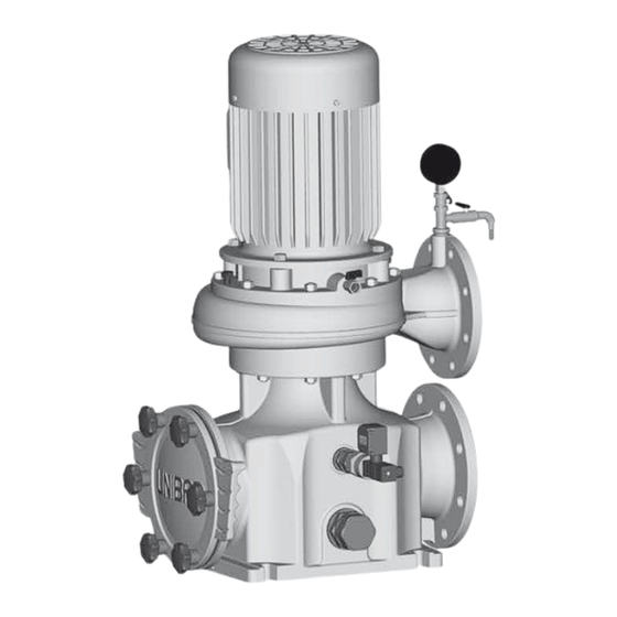
- Page 1 UNIBAD Bath water circulating pump Operating manual Model - X - XC - X-PM J.H. Hoffmann GmbH & Co. KG | Littau 3-5 | DE-35745 Herborn +49 (0) 27 72 / 933-0 | +49 (0) 27 72 / 933-100 info@herborner-pumpen.de | www.herborner-pumpen.de Original operating manual A - UX40 GB...
- Page 2 Translation Copyright Deliveries to countries of the EEA require the operating The transfer and duplication of this document and utilisation manual to be translated in accordance with the language and communication of its content is prohibited, unless ex- spoken in the respective country. plicitly stated otherwise.
- Page 3 EC Declaration of Conformity Herborner Pumpenfabrik J.H. Hoffmann GmbH & Co. KG Littau 3-5, 35745 Herborn, Germany Ms J. Weygand is authorised to create the technical documentation. Herborner Pumpenfabrik J.H. Hoffmann GmbH & Co. KG J. Weygand Littau 3-5, 35745 Herborn, Germany We hereby declare that the Bath water circulating pump UNIBAD/ -XC/ -PM...
-
Page 5: Table Of Contents
Table of contents Table of contents General information ........6 Commissioning ......... 30 Intended use ..........6 Mounting the screw connection....31 Exploded view ..........7 Adjusting the soiling monitor ....... 31 Wear parts ............. 8 Operating modes and connecting frequen- Technical specifications......... -
Page 6: General Information
General information General information Danger! Intended use Pumping flammable or explosive liq- uids is perilous. The swimming pool water circulation pump UNIBAD with inte- grated hair and fibre filter for dirt separation is the centrepiece Do not pump flammable or explosive of modern circulation systems for the delivery and filtering of liquids. -
Page 7: Exploded View
General information Exploded view Model X/X-PM Model XC Figure 1a Exploded view (X/X-PM model) Figure 1b Exploded view (XC model) Only exists in case of design with screw propeller. Only exists in case of design with closed multi vane impeller in material design W3, but not for 200-250/... and 200-270/.. -
Page 8: Wear Parts
General information Individual components Technical specifications Filter casing 1.4.1 Model designation Filter strainer Example: Filter cover 150-270/0304SPXC-PM-W2-V-S Star handle 005.1 Screwed connection 005.2 Screwed connection Nominal diameter of pressure flange DN [mm] Ball valve Design dimensions Pump casing Hydraulic version Intermediate casing Guiding ring Motor rating [kW]... -
Page 9: Impellers
General information 1.4.2 Impellers An existing ETS X4 permits monitoring of the mechanical seal to protect it from dry running. 1.4.5 Drive Open and closed multi vane impellers and screw propellers (SP) for clean to slightly A three-phase motor with squirrel-cage drives the pump. The soiled pumped media are used. -
Page 10: Dimensions, Weight, Performance Data
General information Motor data for model X-PM Ambient temperature range for: lower limit temperature: 5 °C Design IM B5 upper limit temperature: + 40 °C Motor connection Manufacturer-specific Protection type IP 55 Density and viscosity of the pumped medium: Speed 1500 min Density: max. - Page 11 General information Model XC 50/60 Hz P2 [kW] 1500/1800 min 1.5/1.8 49/53 2.2/2.6 49/53 3.0/3.6 49/53 4.0/4.8 49/53 5.5/6.6 49/53 7.5/9.0 49/53 11.0/13.2 50/54 15.0/18.0 50/54 18.5/22.2 52/56 22.0/26.4 52/56 30.0/36.0 52/56 Model X-PM P2 [kW] 1500 min 11.0 15.0 18.5 22.0 30.0...
-
Page 12: Safety
Safety Safety The following signal words represent Notes / explanations This indicates an imminent danger. If it is Danger! not avoided it will result in death or the most The following symbols represent severe of injuries. Warning of a hazardous area This indicates a potentially dangerous situa- Warning! tion. -
Page 13: Integrated Safety Systems (Optional)
Safety ETS X4 An existing ETS X4 (electronic dry running protection system) Important! that uses a vibrating fork sensor prevents the dry running When making any inquiries and ordering spare parts of the slide ring seal. This protects the functionability of the please make sure you specify the pump type and the order pump. -
Page 14: Safety Measures
Safety Safety measures Obligations of the operator This operating manual is part of the machine and, as such, The operator is obligated to: must always be made available to operating personnel. - instruct his/her operating and maintenance personnel with Please make sure that regard to the pump's safety equipment and - you observe the safety precautions it contains, - monitor compliance with the safety measures. -
Page 15: General Hazard Warnings
General hazard warnings General hazard warnings Assembly, operation and maintenance person- Dangers Assembly, operation and maintenance personnel are re- sponsible for the transportation, fitting, installation, operation, cleaning and reparation of the pump. Warning! 1. Only trained and authorised persons may Maintenance and repair work can install and operate the pump. -
Page 16: Shut Off Procedures
General hazard warnings Shut off procedures The following shut off procedure must be complied with before conducting any maintenance, cleaning and/or repair work (only by specialists). Warning! Electric current can result in death. Disconnect the block motor (802) ac- cording to the 5 safety rules. When cleaning close any electrical cabinets that are open to prevent dust or water from entering. -
Page 17: Transport
Transport Transport Packaging for transportation by HGV When the pump is transported by HGV it is packed and Scope of delivery secured on a transport pallet. The detailed scope of delivery can be viewed in the order confirmation. 4.2.2 Intermediate storage The freight packaging of the pump and the spare parts Transport and packaging are suitable for storage for a period of approximately 3... -
Page 18: Transport With A Crane
Transport 4.3.2 Transport with a crane - The crane must be able to support the full weight of the pump. - The operator must be authorised to oper- ate the crane. - Attach the pump to the crane using the corresponding separate lifting accessories (e.g. -
Page 19: Installation / Fitting
Installation / fitting Installation / fitting In order to prevent transferring vibrations to the building and the pipeline system it is recommended to install pipe compensators and vibration dampers. Installation Prepare the construction in accordance with the pump dimensions. Caution! Injuries may be caused when installing Important! the pump. -
Page 20: Dimensions
Installation / fitting Dimensions 5.2.1 Dimensions of X/X-PM model Figure 5a Dimensions (X/X-PM model) Flange position Figure V Figure VL Figure L Figure HL Figure H Figure HR Figure R Figure VR When dismounting the motor ensure there is sufficient room for The terminal box alignment may vary in the case of the design the lifting device. - Page 21 Installation / fitting Model X Model ø k min. min. [kg] 40-221/0114X 40-221/0154X 50-191/0114X 50-191/0154X 50-241/0154X 50-241/0224X 50-241/0304X 65-243/0224X 65-243/0304X 65-243/0404X 65-270/0404X 65-271/0404X 65-270/0554X 65-301/0754X 65-302/0754X 65-302/1104X 80-241/0154X 80-241/0224X 80-241/0304X 80-241/0404X 80-255/0304X 80-255/0404X 80-255/0554X 80-332/1104X 1060 80-332/1504X 1095 100-201/0224X 100-201/0304X 100-211/0304X 100-211/0404X 100-241/0554X...
- Page 22 Installation / fitting Model X-PM Model ø k min. min. [kg] 40-221/0114X-PM 40-221/0154X-PM 50-191/0114X-PM 50-191/0154X-PM 50-241/0154X-PM 50-241/0224X-PM 50-241/0304X-PM 65-243/0224X-PM 65-243/0304X-PM 65-243/0404X-PM 65-270/0404X-PM 65-271/0404X-PM 65-270/0554X-PM 65-301/0754X-PM 65-302/0754X-PM 65-302/1104X-PM 80-241/0154X-PM 80-241/0224X-PM 80-241/0304X-PM 80-241/0404X-PM 80-255/0304X-PM 80-255/0404X-PM 80-255/0554X-PM 80-332/1104X-PM 1060 80-332/1504X-PM 1095 100-201/0224X-PM 100-201/0304X-PM 100-211/0304X-PM 100-211/0404X-PM 100-241/0554X-PM...
-
Page 23: Dimensions Of Xc Model
Installation / fitting 5.2.2 Dimensions of XC model Figure 5b Dimensions (XC model) Flange position Figure V Figure VL Figure L Figure HL Figure H Figure HR Figure R Figure VR When dismounting the motor ensure there is sufficient room for The terminal box alignment may vary according to size. - Page 24 Installation / fitting Model ø k min. min. [kg] 40-221/0154XC 50-191/0154XC 50-241/0154XC 50-241/0224XC 50-241/0304XC 65-243/0224XC 65-243/0304XC 65-243/0404XC 65-270/0404XC 65-271/0404XC 65-270/0554XC 65-301/0754XC 65-302/0754XC 65-302/1104XC 80-241/0154XC 80-241/0224XC 80-241/0304XC 80-241/0404XC 80-255/0304XC 80-255/0404XC 80-255/0554XC 80-332/1104XC 1010 80-332/1504XC 1010 100-201/0224XC 100-201/0304XC 100-211/0304XC 100-211/0404XC 100-241/0554XC 100-241/0754XC 100-271/0554XC 100-271/0754XC 100-331/1104XC...
-
Page 25: Technical Specifications
Installation / fitting Technical specifications 60 Hz: 1800 min (460 V) [kW] I [A] dB(A) Model X 50 Hz: 1500 min (400 V) 13.0 [ kW] I [A] dB(A) 18.2 13.2 23.0 18.0 31.3 22.2 38.6 26.4 44.7 36.0 60.0 11.4 15.4 11.0... -
Page 26: Electrical Connection
Installation / fitting Legend: Warning! Nominal output I Nominal current Electric current can result in death. I Starting current Provide equipotential bonding between Voltage the filter casing and building earth. dB(A): Sound pressure level (complete pump) Electrical connection Motor protection The electrical connection should only be established by an Use a motor circuit breaker or adequate motor protection with electrician. -
Page 27: Change Of Direction Of Rotation
Installation / fitting 5.6.1 Change of direction of rotation Danger! The direction of rotation can be changed by swapping two phases of the motor cable. The rotating impeller can cut or crush hands and arms. Safeguard the pump when checking the direction of rotation. -
Page 28: Ptc Thermistor Connection
Installation / fitting Model X-PM Frequency converter operation Voltage supply via frequency converter Important! Motor voltage/motor frequency W2 U2 Observe the operating instructions included in delivery! (motor name plate) V1 W1 300-400 V 3 50-75 Hz Important! Pumps of the UNIBAD-PM type only for operating frequency converters. -
Page 29: Soiling Monitor Of The Filter Strainer
Installation / fitting 5.12 Frost protection Important! Do not exceed the pipe forces. Notice! The effects of frost can damage the filled pump. Ensure measures are in place for complete ventilation during Empty pumps during prolonged periods of inactivity. the laying procedure. Pressure pipes - lay in a frost-free configuration, - secure and... -
Page 30: Commissioning
Commissioning Commissioning The following label is located in the vicinity of the ball valve (006): Inspect the pump before commissioning and conduct a functional check. When doing this pay special attention to the following: - Turn the motor shaft repeatedly by hand! - Never allow the pump to run dry! - Are the pump and pipelines properly con- nected? -
Page 31: Mounting The Screw Connection
Commissioning Mounting the screw connection The screw connection can be provided with a sealing cover or a connection for a pipeline. Important! Before commissioning, screw in the screw connection (005.1 and 005.2) that lies in the filter strainer (002)! The following label is located above the opening for the screw connection (005.1) in the filter casing (001): Figure 9 Screw connection with sealing cover... -
Page 32: Starting Up
Commissioning Notice! Prolonged operation against closed gate valves heats up the pumped medium and the pump. Open the gate valves before operation. Important! Use a motor circuit breaker or corresponding motor protection with a tripping characteristic according to DIN VDE 0660. Do not exceed ten connecting procedures per hour. -
Page 33: Maintenance / Cleaning
Maintenance / cleaning Maintenance / cleaning The pump is subjected to vibrations during operation, which can cause the screw and clamp connections to become Maintenance and cleaning work should only be implemented loose. Inspect the pump in regular intervals for any loose by specialist personnel. -
Page 34: Maintenance Instructions For Prolonged Periods Of Inactivity
Maintenance / cleaning For pump controllers it is recommended to programme an automatic start up every 48 hours for a maximum of 3 Important! seconds. Collect any waste and emissions in appropriate containers A start up procedure at approximately 5 Hz is advisable for and dispose of them properly. -
Page 35: Greasing Intervals
Maintenance / cleaning The following label is found on the motor if a relubrication unit is present: Important! Use grease guns for conical grease nipple H according to DIN 71412. Observe the lift quantities of the grease guns! 7.3.2 Greasing intervals Anti-friction bearing Anti-friction bearing (drive side) -
Page 36: Cleaning
Maintenance / cleaning Cleaning Disassembly of the filter strainer (002): 1. Detach the star handles (004) to fasten Remove any sediment deposits when dismounting or dis- the filter cover (003). mantling the pump using mechanical means if necessary. Doing this will ensure flawless operation. 2. -
Page 37: Tightening Torques For Nuts And Bolts
Maintenance / cleaning Caution! Important! Dry running the pump will destroy the Check the proper seat of the filter strainer during installa- mechanical seal! tion! Before starting the pump fill the pump The handle of the filter strainer (002) without sealing lip and supply pipe with the pumped generates the necessary prestress through the mounting of medium. -
Page 38: Disturbance / Cause / Trouble Shooting
Disturbance / cause / trouble shooting Disturbance / cause / trouble Disturbance Cause Trouble shooting shooting The delivery of Density of the Dilute the the pump is too pumped medium pumped medium The facts and information described in this manual with low. - Page 39 Disturbance / cause / trouble shooting Disturbance Cause Trouble shooting Disturbance Cause Trouble shooting Pump vibrates or Anti-friction bear- Exchange anti- Bearing becomes Bearing running Top up grease, makes a noise. ing defective. friction bearing. without lubrica- replace bearing if tion: necessary.
-
Page 40: Disassembly / Assembly
Disassembly / assembly Disassembly / assembly Important! The pump is predominantly manufactured from steel. Dis- Refrain from using excessive force while disassembling and pose of the pump, oils and any cleaning agents in accordance assembling the pump. with the applicable local environmental regulations. Cleaning implements (such as brushes, rags, etc.) are to be disposed of in accordance with the applicable environmental regulations or manufacturer's instructions. - Page 41 Disassembly / assembly Emptying the pump UNIBAD-XC: De-aerate the pump by opening the ball valve (006). Then loosen the return pipe (702) on the pump casing (101) in the following way: Loosen the nut (920). Press the pressure ring back- wards.
-
Page 42: Assembly
Disassembly / assembly Important! Nuts (920) with a self-locking plastic ring are to be replaced Pull the intermediate casing when reattaching the impeller. (113) over the motor shaft (819). Important! To reduce friction during assembly lubricate all sliding surfaces of the elastomers with low surface tension water (added detergent). - Page 43 Disassembly / assembly Use assembly aids (acces- Important! sories) (if available) to ensure Do not damage the counter ring of the mechanical seal on an optimal seating of the the thread and change-over of the motor shaft or press at mechanical seal on the motor an angle! shaft (819).
- Page 44 Disassembly / assembly Cooling hose mounting for UNIBAD-XC: Important! Important! Turn back jack screws beforehand. - Shorten the hoses at both ends by approximately 5 mm. Place the gasket (400) or This ensures precise sealing. O-ring (412.2) between the - Re-close the ball valve (006) after assembly. pump casing (101) and the intermediate casing (113).
Need help?
Do you have a question about the UNIBAD-X and is the answer not in the manual?
Questions and answers