Table of Contents
Advertisement
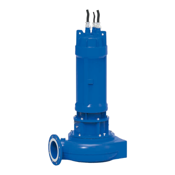
UNIVERS-T
Operating manual
The single-stage submerged motor pump for sewage:
compact, powerful and effective at the same time.
Translation of the original
operating manual
A-RT 33 GB
Herborner Pumpentechnik GmbH & Co KG | Littau 3-5 | DE-35745 Herborn | Phone: +49 (0) 27 72 / 933-0
Fax: +49 (0) 27 72 / 933-100 | E-mail: info@herborner-pumpen.de | www.herborner-pumpen.de
Advertisement
Table of Contents

Related Manuals for HERBORNER pumpentechnik UNIVERS-T


Summary of Contents for HERBORNER pumpentechnik UNIVERS-T
- Page 1 Translation of the original operating manual A-RT 33 GB Herborner Pumpentechnik GmbH & Co KG | Littau 3-5 | DE-35745 Herborn | Phone: +49 (0) 27 72 / 933-0 Fax: +49 (0) 27 72 / 933-100 | E-mail: info@herborner-pumpen.de | www.herborner-pumpen.de...
- Page 2 Copyright The transfer and duplication of this document and utilisation and communication of its content is prohibited, unless expli- citly stated otherwise. Non-compliance with this stipulation will result in compensation for damages. All rights reserved.
- Page 3 - Directive 2014/34/EU (for explosion protection version) Herborn, 20/04/2016 ..............Signature (Management) Original Herborner Pumpentechnik GmbH & Co KG | Littau 3-5 | DE-35745 Herborn | Phone: +49 (0) 27 72 / 933-0 Fax: +49 (0) 27 72 / 933-100 | E-mail: info@herborner-pumpen.de | www.herborner-pumpen.de...
-
Page 4: Table Of Contents
UNISCHACHT installation example .... 22 Dimensions ..........23 5.2.1 Dimensions wet-well installation ....23 Technical data ..........27 5.3.1 Technical data UNIVERS-T ......27 5.3.2 Motor data UNIVERS-T-SG ......32 5.3.3 Motor data UNIVERS-T-PO ......33 Cable connection ........34 Electrical connection ........ -
Page 5: General Information
Intended use Pumping flammable or explosive li- quids is life-threatening. The close coupled sewage pump UNIVERS-T is predomi- nantly used in process engineering plants. It is especially Only use pumps of explosion-proof suitable for delivering uncleaned waste water and sewage. - Page 6 General information The explosion protection marking on the pump refers only to the pumping component. The motor has its own explosion Important! protection marking. Intended use also includes complying with the operating and maintenance conditions specified by the manufacturer. The explosion-proof centrifugal pumps satisfy the require- ments of electrical equipment for use in potentially explosive atmospheres in accordance with Directive 94/9/EC of the European Council dated 23 Mar-...
-
Page 7: Exploded View
General information Exploded view Installation T Installation S DN 50/150 320.1 410.1 320.2 433.2 412.2 903.5 551.2 410.2 400.3 932.2 903.6 DN 200/300 903.4 903.3 433.1 551.1 932.1 400.2 412.1 900.2 412.3 903.2 903.1 Figure 1b Exploded view (S model) 400.1 Installation H 900.1... -
Page 8: Wear Parts
General information Individual components Wear parts Star handle The specifications relating to the selection of wear parts are based on the demand for a two-year operation in accordance Seal electrode with DIN 24296 (pump and pump units for liquids - spare duck foot parts - selection and procurement). -
Page 9: Technical Data
General information Technical data 1.4.1 Model designation Example: TWRH/101/2-6SP-240-PO-C-EX-T-W1-S design sub- merged motor pump for se- wage Impeller type = Open single and twin vane impeller = Closed multi vane impeller W = Vortex impeller Construction series UNIVERS Pump model = small = medium = large... -
Page 10: Impellers
The intermediate Rubber coated vortex impeller (W) for ab- casing is filled with lubricating oil to lubricate and cool the rasive pumping media (UNIVERS-T-SG). mechanical seals. This oil even enables a short-term dry run. The intermediate casing can be optionally monitored for leaks using a sealing electrode. -
Page 11: Drive
General information The exact motor data can be found on the name plate. Danger! Air bubbles or accumulations of gas around the mechanical seal create a potentially fatal explosive atmosphere. Caution! Provide a constant supply of pumped Impermissible heating will damage the media to the supply and pressure pipes three-phase motor. - Page 12 Safety 1.4.7 General data Media temperature range for: Lower limit temperature: 5 °C Upper limit temperature: + 40°C Density and viscosity of the pumped medium: Density: max. 1000 kg/m Kinematic viscosity: max. 1 mm /s (1 cST) Customer-specific solutions may differ from this standard data.
-
Page 13: Safety
Safety Safety The following signal words represent Notes/explanations This indicates an imminent danger. If it is not Danger! avoided, it will result in fatal injury or serious The following symbols represent personal injuries. Warning of a hazardous area This indicates a potentially dangerous situa- Warning! tion. -
Page 14: Integrated Safety Systems (Optional)
Safety Integrated safety systems (optional) Important! Check the integrated safety devices at regular intervals j = annually. When making any enquiries or ordering spare parts, please The inspection methods applied here are: make sure you specify the pump type and the order number. S = Visual inspection, F = Functional check. -
Page 15: Connections On The Pump
Safety Connections on the pump Important! A trained person is understood to be someone who - has been instructed by a specialist about the tasks they are assigned and the possible dangers associated with improper conduct, - has received practical training, if necessary, and - has been informed about the necessary protective equip- ment and precautions. - Page 16 Safety The operating company has to obtain local operating licences and observe the associated conditions. In addition, they must comply with the local statutory pro- visions for - the safety of personnel (accident preven- tion regulations) - the safety of operating equipment (protec- tive equipment and maintenance) - product disposal (waste management legislation)
-
Page 17: General Hazard Warnings
General hazard warnings General Hazard Warnings Assembly, operation and maintenance personnel Assembly, operation and maintenance personnel are re- Dangers sponsible for the transportation, fitting, installation, operation, cleaning and trouble shooting of the pump. 1. Only trained and authorised persons are Warning! allowed to install and operate the pump. -
Page 18: Shut-Off Procedures
General hazard warnings Shut-off procedures The following shut-off procedure must be complied with before conducting any maintenance, cleaning and/or repair work (by specialists only). Warning! Electric current can result in fatal injury. Disconnect the block motor (805) according to the 5 safety rules. When cleaning, close any electrical cabinets that are open to prevent dust or water from entering. -
Page 19: Transport
Transport Transport Packaging for transportation by HGV When the pump is transported by HGV, it is packed and Scope of delivery secured on a transport pallet. The detailed scope of delivery is in the order confirmation. 4.2.2 Intermediate storage Transport and packaging The freight packaging of the pump and the spare parts is sui- table for storage for a period of approximately three months. -
Page 20: Transportation With A Forklift Truck
Transport 4.3.1 Transportation with a forklift truck - The forklift must be designed to support the weight of the pump. - The driver must be authorised to operate the forklift truck. 4.3.2 Transportation with a crane - The crane must be able to support the full weight of the pump. -
Page 21: Installation/Fitting
Installation/fitting Installation/Fitting The c able duct to the connector should Installation be sealed so it is gas-impermeable af- ter the inserting the cables and control Prepare for construction in accordance with the pump di- lines through foam padding. mensions. Important! Provide sufficient space for maintenance and repair pro- Observe the safety regulations for wor- cedures. -
Page 22: Unischacht Installation Example
Installation/fitting 5.1.1 UNISCHACHT installation example Figure 5 Unischacht 1 Shaft cover 2 Ventilation and aeration 3 Shaft cover 4 Sleeve for cable protection tube controller 5 Chain 6 Supply 7 Level contol 8 Submersible motor pump 9 Concrete shaft 10 Supporting duck foot 11 Guide tube 12 Pressure tube 13 Flap trap... -
Page 23: Figure 6B
Installation/fitting Dimensions 5.2.1 Dimensions and wet installation Design S (DN 200/300) Design S (DN 50-150) min. ø/ □ h min. ø/ h □ □ min. □ min. min. Ex max. 250 max. 250 min. Ex min. min. Figure 6a Dimensions (S model) single pump station Design T DN 300 on request... - Page 24 Installation/fitting Model TQRH/ 50 1 1/2 TQR/ 1 1/2 TWR/ 1 1/2 TQRS/ 81 1 1/2 TWRS/ 81 1 1/2 TQRH/ 81 1 1/2 TWRH/ 81 1 1/2 TWRH/ 81 - SG 1 1/2 TQR/ 1 1/2 1090 TWR/ 1 1/2 1090 TWR/ 81 - SG...
- Page 25 Installation/fitting Model TQRH/ 50 700x700 TQR/ 700x700 TWR/ 700x700 TQRS/ 81 700x1000 TWRS/ 81 700x1000 TQRH/ 81 700x1000 TWRH/ 81 700x1000 TWRH/ 81 - SG 700x1000 TQR/ 700x1000 TWR/ 700x1000 TWR/ 81 - SG 700x1000 TQRX/ 82 700x1000 TWRX/ 82 700x1000 TWRX/ 82 - SG 700x1000...
-
Page 26: Figure
Installation/fitting 5.2.2 Dimensions installation H Design H max. m Figure 6d Dimensions (H model) Model TQRH/ 50 TQR/ TWR/ TQRS/ 81 TWRS/ 81 TQRH/ 81 110.5 TWRH/ 81 110.5 TWRH/ 81 - SG 110.5 TQR/ 2) 3) 112.5 TWR/ 2) 3) 112.5 TWR/ 81 - SG 3) -
Page 27: Technical Data
Installation/fitting Technical data 5.3.1 Technical data UNIVERS-T 50 Hz: 960 rpm (60 Hz: 1160 rpm) Standard 50Hz Standard 60Hz (Ex) 50 Hz Model approx. P2[kW] I [A] m[kg] prox. P2[kW] I [A] m[kg] prox. P2[kW] I [A] m[kg] TQRH/80 (1.3) (3.7) - Page 28 Installation/fitting 50 Hz: 960 rpm (60 Hz: 1160 rpm) Standard 50Hz Standard 60Hz (Ex) 50 Hz Model approx. P2[kW] I [A] m[kg] prox. P2[kW] I [A] m[kg] prox. P2[kW] I [A] m[kg] TQRH/ 200 (18.5) (37.4) (509) (7.5) (21.0) (35.7) (509) (7.5) (18.5)
- Page 29 Installation/fitting 50Hz: 1450 rpm (60 Hz: 1750 rpm) Standard 50Hz Standard 60Hz (Ex) 50 Hz Model approx. approx. P2[kW] I [A] m[kg] P2[kW] I [A] m[kg] prox. P2[kW] I [A] m[kg] TQRH/ 50 1.5(-) 1.8(-) 1.5(-) TQR/ 1.5(-) 1.8(-) 1.5(-) TWR/ 1.5(-) 1.8(-)
- Page 30 Installation/fitting 50Hz: 1450 rpm (60 Hz: 1750 rpm) Standard 50Hz Standard 60Hz (Ex) 50 Hz Model approx. approx. P2[kW] I [A] m[kg] P2[kW] I [A] m[kg] prox. P2[kW] I [A] m[kg] TQRH/ 151 18.5(-) 38.2 10.2 18.5(-) 37.4 10.2 TQRH/ 151 22.0(-) 46.0 10.2...
- Page 31 Installation/fitting 50Hz: 2900 rpm (60 Hz: 3600 rpm) Standard 50Hz Standard 60Hz (Ex) 50 Hz Model approx. approx. approx. P2[kW] I [A] m[kg] P2[kW] I [A] m[kg] P2[kW] I [A] m[kg] TQRH/ 50 2.2(-) 2.6(-) 2.2(-) 4.75 TQRH/ 50 3.6(-) TQRH/ 50 4.8(-) TQR/...
-
Page 32: Motor Data Univers-T-Sg
Installation/fitting 5.3.2 motor data UNIVERS-T-SG 50Hz: 960 rpm (60 Hz: 1160 rpm) Standard 50Hz Standard 60Hz (Ex) 50 Hz Model approx. approx. P2[kW] I [A] m[kg] P2[kW] I [A] m[kg] prox. P2[kW] I [A] m[kg] TWRH/ 81 0.75(0.75) 79(106) 1(2a) 0.9(0.9) -
Page 33: Motor Data Univers-T-Po
Installation/fitting 5.3.3 motor data UNIVERS-T-PO 50Hz: 960 rpm (60 Hz: 1160 rpm) Standard 50Hz Standard 60Hz (Ex) 50 Hz Model approx. approx. approx. P2[kW] I [A] m[kg] P2[kW] I [A] m[kg] P2[kW] I [A] m[kg] TWRH/ 101 1.1(1.1) 106(131) 1(2a) 1.3(1.3) -
Page 34: Cable Connection
Installation/fitting cable connection Motor connection No. 1 Motor connection No. 2 Motor connection No. 3 Motor connection No. 4 H07RN-F7G1,5 4a - H07RN-F10G1,5 4b - H07RN-F10G2,5 Motor connection No. 5 Motor connection No. 6 H07RN-F10G1,5 [2x] A07RN-F4X4+2x0,75 Motor connection No. 7 Motor connection No. - Page 35 Installation/fitting Motor connection No. 9 Motor connection No. 10 9a - [2x] H07RN-F4G6 + [1x] H07RN-F5G1,5 H07RN-F10G1,5 9b - [2x] H07RN-F4G10 + [1x] H07RN-F5G1,5 13 - [2x] H07RN-F4G16 + [1x] H07RN-F5G1,5 14 - [2x] H07RN-F4G50 + [1x] H07RN-F5G1,5 Motor connection No. 11 Motor connection No.
-
Page 36: Electrical Connection
Installation/fitting Electrical connection Warning! The electrical connection should only be carried out by a qualified electrician. Electric current can result in fatal injury. Warning! The pump should be safeguard with an appropriate pre- An incorrect electrical connection can fuse (according to nominal capacity of the motor). In pump result in fatal injury. -
Page 37: Direction Of Rotation Check
Installation/fitting Danger! Important! Risk of a potentially fatal explosion The motor circuit breaker should be during the installation phase. - regulated for nominal motor current during direct starting, The rotaion direction test mus be per- - introduced into the delta link for star-delta starting and set formed outside of the area identified as to a maximum of 0.58-times the nominal current. -
Page 38: Changes In Direction Of Rotation
Installation/fitting 5.7.1 Changes in direction of rotation The direction of rotation can be changed by swapping two phases of the motor cable. Motor connection diagrams Caution! An incorrect electrical circuit arrange- ment will result in breakdown of the three-phase motor. Observe the circuit arrangement. -
Page 39: Ptc Thermistor Connection (Option)
Installation/fitting 5.8.1 PTC thermistor connection Ensure measures are in place for complete ventilation during the laying procedure. Pressure pipe Important! - lay frost-free, - Measurement voltage of max. 2.5 V DC! - secure and - Only operate in conjunction with a tripping unit. - connect so they are stress-free. -
Page 40: Commissioning
Commissioning Commissioning Danger! Inspect the pump before commissioning and carry out a Air bubbles or accumulations of gas functional check. When doing this, pay special attention to around the mechanical seal create a the following: potentially fatal explosive atmosphere. - Turn the motor shaft several times by Provide a constant supply of pumped hand. -
Page 41: Starting Up
Commissioning The permissible switch frequency per hour is shown in the following table, if the factory has not indicated otherwise. Important! Use a motor circuit breaker or appropriate motor protection with a tripping characteristic according to DIN VDE 0660. Motor rating [kW] Max switches [h] at an interval [min] Contact the respective manufacturer with regard to the per-... -
Page 42: Maintenance/Cleaning
Maintenance/cleaning Maintenance/Cleaning Notice! Maintenance and cleaning work should only be carried out Pumped media can be hazardous to people's health. by specialist personnel. These personnel must be provided with personal protective equipment (e.g. protective gloves). Always wear personal protective equipment such as protec- tive gloves and goggles. -
Page 43: Maintenance Instructions During Prolonged Periods Of Inactivity
Maintenance/cleaning Maintenance instructions during prolonged peri- ods of inactivity Danger! Protect the pumps from exposure to the weather (UV rays, Flying sparks may cause a potentially sunlight, high humidity levels, frost, etc.). fatal explosion. The points in section 6 ‘Commissioning’ must be fulfilled Before dismantling the pump in po- before recommissioning the pumps. -
Page 44: Bearing Lubrication
Maintenance/cleaning Bearing lubrication Seals Anti-friction bearings are supplied pre-lubricated. In general, a mechanical seal does not require any main- tenance. Only replace the mechanical seal as a complete unit. This ensures optimum shaft sealing. Important! Anti-friction bearings that are used at a speed of - 960/1450 (1160/1750) rpm are to be re-lubricated or re- Danger! placed, if necessary, after 20,000 hours of operation... -
Page 45: Tightening Torques For Bolts And
Maintenance/cleaning Tightening torques for nuts and bolts Non-stainless Stainless (A4) Danger! Thread 10.9 [Nm] [Nm] [Nm] Impermissible heating of the three- 18.5 23.0 32.0 phase motor can create a potentially 45.0 46.0 64.0 fatal explosive atmosphere. 70.0 80.0 110.0 It is imperative that the motor is kept 135.0 195.0 275.0... -
Page 46: Disposal
Maintenance/cleaning Disposal Important! If no return or disposal agreements have been made, take the dismantled components for recycling: - Use oil types according to ISO VG 46. - Scrap the metal. - Use physiologically harmless oils and grease when using - Recycle the plastic elements. -
Page 47: Disturbance/Cause/Trouble Shooting
Disturbance/cause/trouble shooting Disturbance/Cause/Trouble Disturbance Cause Trouble shoo- Shooting ting Head too high. Check the plant The facts and information in this manual regarding “Di- for any impurities sturbance, Cause and Trouble Shooting” are addressed to and/or the selec- specialists (as defined in section 2.4 ‘Safety measures’) in tion of the pump. - Page 48 Disturbance/cause/trouble shooting Disturbance Cause Trouble shoo- Disturbance Cause Trouble shoo- ting ting Pump doesn't Check the opera- Motor connected Connect motor to operate in the ting conditions. incorrectly. existing operating specified opera- voltage. ting range. Bearing gets hot Bearing running Top up grease, Pump vibrates or Anti-friction bea-...
-
Page 49: Disassembly/Assembly
Disassembly/assembly Disassembly/Assembly Disassembly It is possible to disassemble the interchangeable module The pump is made mainly of steel. Dispose of the pump, oils of the pump (see section 1.2 ‘Exploded view’) without dis- and any cleaning agents in accordance with applicable local connecting the intake connection and pressure flange from environmental protection regulations. - Page 50 Disassembly/assembly Loosen the connecting bolts from the pump casing (101) Loosen (900.1) bolt. and intermediate casing (113). Prise the complete interchan- geable module on the inter- remove Screw locking device mediate casing (113) from the (930) centering of the pump casing (101) using two jack screws.
- Page 51 Disassembly/assembly Notice! A damaged fitting surface does not guarantee a precise seal. Do not damage the seating for the O-ring. Remove the circlip (932.1) with circlip pliers. Remove all components of the mechanical seal (433.1) from the intermediate casing (113). Remove the spacer disc (551.1).
- Page 52 Disassembly/assembly 16.2.2 16.3.3 Remove all components of the mechanical seal (433.1) Remove the spacer disc from the flange-type end (551.2) (if there is one). shield of the submersible motor (805). 16.2.3 Clean the chrome-nickel steel motor shaft of any residue and sediment deposits using an ultra-fine emery cloth.
-
Page 53: Assembly
Disassembly/assembly When inserting the pressure-sensitive counter ring, ensure 1.2.2 - an even distribution of pressure, - you use a clean pin with a soft seating and Slide the sliding ring unit - that there are no foreign particles on the sliding surfaces. with smooth polished surface carefully onto the shaft to the counter ring. - Page 54 Disassembly/assembly 1.3.2 Important! Important! Comply with squareness tolerance of 0.1 mm! Do not damage the counter ring of the mechanical seal on the thread and transition of the motor shaft or press it at an angle! Carefully slide the sliding ring unit over the shaft to the Position the O-ring (412.2) counter ring.
- Page 55 Disassembly/assembly Use the circlip pliers to clamp the circlip (932.1) into the Tighten the screw (900.1). groove on the motor shaft (819). Important! Insert the key (940) into the - Too large an air gap significantly reduces the performance motor shaft groove. of the pump.
- Page 56 Disassembly/assembly Fill oil into the opening of the screwed plug (903.3). Leave an air gap between the pump casing wall and oil level. Information about oil quantities is listed in section 7.8 Oil filling and oil change. Then replace the screwed plug (903.3) again.
Need help?
Do you have a question about the UNIVERS-T and is the answer not in the manual?
Questions and answers