
Related Manuals for Ashly CA Series


Summary of Contents for Ashly CA Series
- Page 1 Operating Manual CA SERIES CA-502 CA-504 CA-1.02 CA-1.04 CA-1.52 CA-1.54 2- and 4-channel Power Amplifier...
- Page 2 CA Amplifier • Operating Manual CA Amplifier • Operating Manual Important Safety Instructions • Consignes de sécurité à lire attentivement Read these instructions. n’accepte pas la fiche, consulter un électricien pour qu’il Keep these instructions. The lightning flash with arrowhead symbol, within Le symbole de la flèche dans un triangle équilateral remplace la prise désuète.
- Page 3 The warranty covers every product generates, uses and can radiate radio and packing materials are not available for with the Ashly brand name, and is offered at no frequency energy and, if not installed and inspection by the carrier. Save all packing extra cost to you.
-
Page 4: Table Of Contents
• Input gain settings per channel: 26dB, 32dB, 38dB, or 1.4V Introduction ....4 Thank you for your purchase of this Ashly CA • Remote DC level control per channel power amplifier. This product uses state of the Requirements ....4 art, light weight, high power, high efficiency •... -
Page 5: Input Wiring
CA Amplifier • Operating Manual powered up. The model number and power level signal wires in close proximity or parallel The following table lists the resistance per 100 consumption are indicated on the back panel to long speaker cables, AC power cables, or feet of common copper wire gauges, and also label placed near the AC inlet. -
Page 6: Remote Control Wire
CA Amplifier • Operating Manual Remote Control Wire Cooling Air vents on the amplifier front and side • Remote DC level control - Bell or telephone panels must have access to free flowing room wire is sufficient for DC level control, as well as temperature air. -
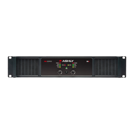
Page 7: Front Panel Features
CA Amplifier • Operating Manual Front Panel Features CA-1.54 shown Air Vents Cool air enters in through the amplifier sides and is vented out the front. Channel LED Indicators • CLIP/MUTE (red): CLIPPING is indicated when the speaker output reaches 95% (-0.5dB) of maximum power. -
Page 8: Rear Panel Features
CA Amplifier • Operating Manual Rear Panel Features CA-1.54 shown Standby Connector This Euroblock connector is used for remote contact closure control of amplifier standby status, which places the amplifier into a low power consumption state. A DIP switch sets standby circuit polarity. -
Page 9: Combo Input Jacks
>9dB Continuous Power Limiting AC Mains Connector Amp Power Module Channel Protect Always use the AC cord provided by Ashly Thermal Protect for connecting to mains power. The amplifier † auto-detects mains voltage from 100VAC to Power Supply Out Of Range ††... - Page 10 CA Amplifier • Operating Manual Specifications General Power Amplifier Specifications (0dBu = 0.775V rms) Amplifier Model CA1.54 CA1.52 CA1.04 CA1.02 CA504 CA502 Maximum Output Power - in Watts CEA-2006/490A, 20ms 1kHz 1%THD+N, 480ms 1kHz -20dB, 120VAC, all channels driven at rated load Low Z output, per channel 2 Ohm 1500...
-
Page 11: Specifications
CA Amplifier • Operating Manual Specifications (continued) Distortion (SMPTE, typical) <0.5% Disable LED (yellow) On when front panel controls are Distortion (THD-N, typical, 8 Ohm, <0.5% disabled, Off 10dB below rated power, 20Hz-20kHz Attenuators Per channel: front panel, Signal to Noise, 26dB input sensitivity, >98dB (50x models), Fully off = Mute 20Hz-20kHz, unweighted... -
Page 12: Warranty
Phone: (585) 872-0010 Fax: (585) 872-0739 Toll Free (800) 828-6308 www.ashly.com ©2020 Ashly Audio, Inc. All rights reserved worldwide. Ashly Audio is a division of Jam Industries, Ltd. All features, specifications, and graphical representations are subject to change or improvement without notice. CA R0 0220...
Need help?
Do you have a question about the CA Series and is the answer not in the manual?
Questions and answers