
Related Manuals for Clearfield FieldSmart FiberFlex 2000


Summary of Contents for Clearfield FieldSmart FiberFlex 2000
- Page 1 FieldSmart FiberFlex 2000 ® Installation Manual ______________________________________________________ Manual 021574 Rev A - May 2020...
-
Page 2: Table Of Contents
Installing a Pre-Cast Concrete Pad Pre-Cast Pad Requirements Preparing the Site Installing a Pre-Cast Pad Installing a Foundation Vault Foundation Vault Requirements Preparing the Site Installing the Foundation Vault Proprietary Information: Not for use or disclosure except by written agreement with Clearfield. - Page 3 FieldSmart FiberFlex 2000 ® Installation Manual __________________________________________________________ Chapter 4: Installing the Cabinet Unpacking the Cabinet Operating Cabinet Doors Preparing the Cabinet for Installation Installing the Cabinet on a Concrete Pad Removing the Lifting Details Chapter 5: Installing Local AC Power Installing the Cabinet Ground Connection Installing AC Power (220-240 VAC) Chapter 6: Installing Outside Plant Cables...
- Page 4 Replacing AC Breakers Replacing Rectifier Modules Replacing Batteries Replacing a Battery Heater Appendix A: Reference Information Specifications Supported Batteries Wiring Diagrams Standard Warranty Proprietary Notice Technical Support Proprietary Information: Not for use or disclosure except by written agreement with Clearfield.
-
Page 5: About This Guide
__________________________________________________________ About This Guide This document provides a general installation practice for the Clearfield FiberFlex 2000 outdoor cabinet. This document also provides a general description of the cabinet and its subsystems, guidance for planning, site preparation, power installation, splicing to the outside plant, component installation and expansion, and cabinet maintenance. -
Page 6: Chapter 1: Fiberflex 2000 Product Overview
® Installation Manual _________________________________________________________ Chapter 1: FiberFlex 2000 Product Overview This chapter provides a general description of the Clearfield FiberFlex 2000 outdoor cabinet, including its standard features and options. Topics Covered This chapter provides a general description of the Clearfield... -
Page 7: Cabinet Description
FiberFlex 2000 ® Installation Manual __________________________________________________________ Cabinet Description The Clearfield FiberFlex 2000 cabinet is an environmentally-controlled outdoor enclosure designed to house and protect network electronics equipment. Use the FiberFlex 2000 to provide services from a remote node location deep inside the customer serving area, beyond the direct reach of the carrier Central Office. -
Page 8: Cabinet Features
Fuse-protected DC supply to equipment • Battery backup in separate vented compartment • Up to 155 Ah battery reserve capacity (breaker-protected); up to 310 Ah capacity with second-string riser option Proprietary Information: Not for use or disclosure except by written agreement with Clearfield. -
Page 9: Cabinet Options
Common options for the FiberFlex 2000 cabinet include: Enclosure Mounting • Concrete pad mounting: pre-cast or site-cast pad (using Clearfield pad template) • Foundation vault mounting (third-party supplied) Fiber Management • High density fiber management options (144 and 288 fiber distribution panels, 1:32 PON splitters,... -
Page 10: Cabinet Dimensions And Weights
89 cm The approximate weight of the FiberFlex 2000 cabinet is shown below. Configuration Weight (SAE) Weight (Metric) FF2K (single string 155 Ah batteries) 222 lb 101 kg Proprietary Information: Not for use or disclosure except by written agreement with Clearfield. -
Page 11: Cabinet Views
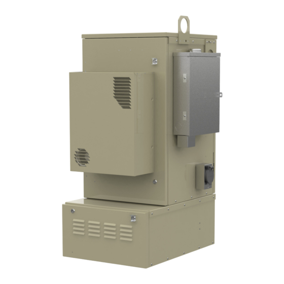
FieldSmart FiberFlex 2000 ® Installation Manual __________________________________________________________ Cabinet Views Views of the FiberFlex 2000 cabinet follow. Front Compartment The front compartment provides access to the electronics equipment, cabinet power system, and fiber management. The cabinet power system consists of a side mounted AC load center option. For fiber access, the fiber management accesso- ries may vary greatly according to the ordered options. - Page 12 Configured cabinets include a battery base compartment for housing one string of front-access VRLA batteries. Battery compartment interior dimensions (for batteries): 11.3” (H) x 20.2” (W) x 21.5” (D) Proprietary Information: Not for use or disclosure except by written agreement with Clearfield.
-
Page 13: Chapter 2: Installation Considerations
FieldSmart FiberFlex 2000 ® Installation Manual __________________________________________________________ Chapter 2: Installation Considerations This chapter provides general considerations for cabinet installation. Review this information before starting the cabinet installation process. Topics Covered This chapter covers the following topics: • Installation process overview •... -
Page 14: Installation Process Overview
FieldSmart FiberFlex 2000 ® Installation Manual _________________________________________________________ Installation Process Overview The cabinet installation process involves the following high-level steps: Proprietary Information: Not for use or disclosure except by written agreement with Clearfield. -
Page 15: Installation Guidelines
FieldSmart FiberFlex 2000 ® Installation Manual __________________________________________________________ Installation Guidelines Review the following guidelines before starting installation activities. General Guidelines Follow these general guidelines and practices: • Read this document completely before starting any installation activities. • Only qualified personnel should perform the procedures described in this document. •... -
Page 16: Space Requirements
The minimum clearance area around the cabinet site must be free of permanent impediments to allow full swing of the cabinet doors. This area must be kept clear of obstructions at all times to provide adequate access for all installation and maintenance activities. Proprietary Information: Not for use or disclosure except by written agreement with Clearfield. -
Page 17: General Safety Recommendations
FieldSmart FiberFlex 2000 ® Installation Manual __________________________________________________________ General Safety Recommendations WARNING! Only trained, qualified technical personnel should perform the procedures described in this doc- ument. These procedures involve potentially hazardous activities, including handling of heavy equipment and exposure to high electrical energy, which could cause injury to untrained personnel. DANGER! Risk of high power current surge and electric shock. -
Page 18: Installation Kit
Installation Manual _________________________________________________________ Installation Kit Clearfield supplies an installation kit with the cabinet that includes materials required for installation. The installation kit contents are listed below. Check to verify that your kit contains all of the listed items.: Item Description Telco hex key, 5/16”... -
Page 19: User-Supplied Items
FieldSmart FiberFlex 2000 ® Installation Manual __________________________________________________________ User-Supplied Items Supply the following items for cabinet installation. Tools Bring the following tools to the installation site: • Power drill with universal socket and screwdriver bit sets • Socket wrench/nut driver set (standard) •... -
Page 20: Cabling Requirements
8–10 AWG stranded copper; Follow National Electric Code (NEC) and local codes (local power) Proprietary Information: Not for use or disclosure except by written agreement with Clearfield. Note: Local climatic conditions, site conditions, or local practices may require adjustments to cabling requirements. -
Page 21: Chapter 3: Preparing The Installation Site
A composite foundation vault, available from a third-party supplier, can provide easy under-cabinet access or serve as a riser. For all mounting configurations, Clearfield requires installation of an earth ground circuit at the installation site to provide lightning protection. Topics Covered This chapter covers the following topics: •... -
Page 22: Installing A Ground Circuit
Installing a Ground Circuit Clearfield requires installing an earth ground circuit (earth electrode) at the installation site to provide protection from electric shock for equipment and personnel. The ground circuit may consist of a simple copper rod driven into the earth or a com- plex system of buried rods and wires. - Page 23 FieldSmart FiberFlex 2000 ® Installation Manual __________________________________________________________ Example of PANI-compliant ground ring with main site ground buss: FiberFlex 2000 Example of PANI-compliant ground ring without a main site ground buss: FiberFlex 2000 Direct: 763.476.6866 • National: 800.422.2537 • www.SeeClearfield.com • techsupport@clfd.net Manual 021574 REV A - June 2020...
- Page 24 Wet soil provides low resistance ground, with resistance increasing as the soil dries. Rock, gravel, sand, loam and clay react differently to wet/dry conditions. Follow local code to satisfy additional requirements, if applicable. Proprietary Information: Not for use or disclosure except by written agreement with Clearfield.
-
Page 25: Constructing A Concrete Pad
Construct a concrete foundation pad for the cabinet at the installation site. Pad construction requires excavating the site, trenching cable conduit, constructing a form, and casting concrete. Use the Clearfield -supplied cast-in-place template to provide exact locations for the mounting studs that anchor the cabinet to the pad and to provide the cable conduit locations. - Page 26 FieldSmart FiberFlex 2000 ® Installation Manual _________________________________________________________ Pad Drawings Use the following drawings for reference during pad construction. Proprietary Information: Not for use or disclosure except by written agreement with Clearfield.
- Page 27 Conduit for outside plant cable (fiber). c. Earth ground wire d. Conduit for AC cable Use the Clearfield cast-in-place template to provide precise conduit orientation. Direct: 763.476.6866 • National: 800.422.2537 • www.SeeClearfield.com • techsupport@clfd.net Manual 021574 REV A - June 2020...
-
Page 28: Assembling The Cast-In-Place Template
Step 4: Attach the short and long brackets together using the eight supplied screws, as shown. Step 5: Tighten all screws to complete the template assembly. Proprietary Information: Not for use or disclosure except by written agreement with Clearfield. -
Page 29: Preparing The Site
Step 3: Place and tie rebar inside the form elevated above the gravel. Step 4: Place the Clearfield cast-in-place template into the form, guiding the cable conduits through the conduit entry ducts in the template. Step 5: Align the template mounting brackets flush with the top of the form, then nail the template to the form to secure it in place. -
Page 30: Casting The Pad
Backfill and grade the perimeter area around the pad with soil, as required. Step 8: Trim the cable conduits to a height no more than 4 inches above the pad. Proprietary Information: Not for use or disclosure except by written agreement with Clearfield. -
Page 31: Installing A Pre-Cast Concrete Pad
Pre-cast pads ship configured with conduit entry cutouts and mounting fixtures (threaded inserts) for anchoring the cabinet to the pad. Specific features and dimensions vary by manufacturer. Contact your sales representative for a list of Clearfield -certified suppliers. - Page 32 Pad Drawings Use the following drawings for reference during site preparation. Actual pad dimensions may vary by manufacturer. Refer to the manufacturer’s documentation for more information. Pad Size Proprietary Information: Not for use or disclosure except by written agreement with Clearfield.
- Page 33 FieldSmart FiberFlex 2000 ® Installation Manual __________________________________________________________ Pad Cross-Section (from left side) For proper cable entry into the cabinet, place conduit into the following locations. a. Conduit for outside plant cable (fiber). b. Conduit for outside plant cable (fiber). c. Earth ground wire d.
-
Page 34: Preparing The Site
Note: When installed, the pad should stand at least one inch above grade. Adjust the compaction and gravel depth accordingly, based on the pad height. Proprietary Information: Not for use or disclosure except by written agreement with Clearfield. -
Page 35: Installing A Pre-Cast Pad
FieldSmart FiberFlex 2000 ® Installation Manual __________________________________________________________ Installing a Pre-Cast Pad Install the pre-cast pad according to the manufacturer’s instructions (typically supplied with the pad). A general installation practice is described below for reference. Adapt the instructions as needed for local requirements, practices, or conditions. -
Page 36: Installing A Foundation Vault
Use 2-inch conduit (maximum) for AC cable. See drawing below for entry location. • Include pull cords in all cable conduits. Refer to the vault manufacturer’s instructions for additional guidelines Proprietary Information: Not for use or disclosure except by written agreement with Clearfield. -
Page 37: Preparing The Site
FieldSmart FiberFlex 2000 ® Installation Manual __________________________________________________________ Preparing the Site Prepare the site for installation of a foundation vault. Some vaults may require custom preparations. Refer to the manufacturer’s instructions for more information. A general practice is described below for reference. Adapt the instructions as needed for local requirements, practices, or conditions. -
Page 38: Installing The Foundation Vault
Step 5: Backfill and grade around the vault perimeter with soil to secure it in place. Step 6: Verify that the vault remains level. Adjust as required. Proprietary Information: Not for use or disclosure except by written agreement with Clearfield. -
Page 39: Chapter 4: Installing The Cabinet
® Installation Manual __________________________________________________________ Chapter 4: Installing the Cabinet This chapter describes how to install the Clearfield FiberFlex 2000 cabinet onto its permanent mounting location. Topics Covered This chapter covers the following topics: • Installing a ground circuit at the installation site •... -
Page 40: Unpacking The Cabinet
Do not remove the cabinet from the pallet until after it has been delivered to the installation site. However, you can remove the cardboard crating to inspect the cabinet at the staging area, if required. Clearfield recommends keeping the protective packaging in place for transportation. -
Page 41: Operating Cabinet Doors
The cabinet has hinged front and side doors, each equipped with two telco hex-pin latches and a padlock hasp for security. Open and close doors using a Clearfield -supplied telco hex key. Each door is equipped with an alarm switch that monitors the position of the door. When a door on an in-service cabinet is opened, an intrusion alarm reports through the equipment. - Page 42 Step 2: Insert the telco hex key into the door latch. Step 3: While holding the door firmly closed, turn the key clockwise to engage the latch. Proprietary Information: Not for use or disclosure except by written agreement with Clearfield.
-
Page 43: Preparing The Cabinet For Installation
FieldSmart FiberFlex 2000 ® Installation Manual __________________________________________________________ Preparing the Cabinet for Installation Complete the following preparations before installing the cabinet. To prepare the cabinet for installation Step 1: Open the front and rear cabinet doors. Step 2: From the battery compartment, remove the isolation mat and the bag containing the installation hardware. Set them aside for use during installation. -
Page 44: Installing The Cabinet On A Concrete Pad
(with battery compartment) onto the riser. For detailed instructions on installing the cabinet onto the riser, see Installing a 155 Ah Battery Compartment Riser. Proprietary Information: Not for use or disclosure except by written agreement with Clearfield. - Page 45 FieldSmart FiberFlex 2000 ® Installation Manual __________________________________________________________ To install the cabinet (or riser) on a concrete pad Note: The following procedure also applies to installing the optional battery compartment riser onto a concrete pad). Step 1: Sweep the pad free of dirt and debris. Step 2: Install the isolation mat onto the concrete pad.
- Page 46 Verify that the doors open and close freely. If necessary, use shims to level the cabinet or riser. Step 8: Apply silicone caulking to the bottom perimeter of the cabinet or riser. Proprietary Information: Not for use or disclosure except by written agreement with Clearfield.
-
Page 47: Removing The Lifting Details
FieldSmart FiberFlex 2000 ® Installation Manual __________________________________________________________ Removing the Lifting Details After the cabinet is installed, remove the two lifting details from the cabinet. To remove the lifting details Step 1: Locate the two lifting details, attached to the upper left corners of the left and right sides of the cabinet. Step 2: Remove the three bolts securing the first lifting detail to the cabinet. -
Page 48: Chapter 5: Installing Local Ac Power
Install power according to your cabinet configuration type. Topics Covered This chapter covers the following topics: • Installing the cabinet ground connection • Installing local AC power Proprietary Information: Not for use or disclosure except by written agreement with Clearfield. -
Page 49: Installing The Cabinet Ground Connection
You must install the cabinet’s connection to the earth ground circuit before you connect commercial power to the cabinet. Guidelines Clearfield recommends adhering to PANI grounding methods to reduce ground current interaction: • The PANI system divides the ground bar into sections, with one type of conductor in each section: Producers, surge Absorbers, Non-isolated and Isolated (PANI). - Page 50 Attach the earth ground wire’s two-hole lug onto the 3/4-inch ground terminal studs per PANI guidelines. Step 6: Re-connect the nuts to the ground terminal studs and tighten to 26 inch-lbs. of torque. Proprietary Information: Not for use or disclosure except by written agreement with Clearfield.
-
Page 51: Installing Ac Power (220-240 Vac)
FieldSmart FiberFlex 2000 ® Installation Manual __________________________________________________________ Installing AC Power (220-240 VAC) Install 220-240 VAC power as described below. DANGER! High voltage may be present. Risk of electrical shock. Do not apply AC power to the cabinet until the installation process is complete. WARNING! Electrical hazard. - Page 52 Tighten the coupling nut around the AC wires at the bottom of the load center housing. Step 8: Re-install the cover panel on the AC load center. Proprietary Information: Not for use or disclosure except by written agreement with Clearfield.
-
Page 53: Chapter 6: Installing Outside Plant Cables
FieldSmart FiberFlex 2000 ® Installation Manual __________________________________________________________ Chapter 6: Installing Outside Plant Cables This chapter describes how to install outside plant cables into the cabinet, including fiber plant (fiber-optic cables for transport/uplink). Topics Covered This chapter covers the following topics: •... -
Page 54: Bonding Cable Sheaths
Clearfield recommends that you bond optical fiber cable sheaths at the first entrance to the cabinet/enclosure site only (the splice case, or similar), and then isolate the sheaths in the short run between splice point and the Clearfield equipment cabinet/enclosure ground. The short run can then be bonded on either side (the Clearfield ground bar side or splice point side, but not both) per local practice. -
Page 55: Installing Fiber Cable
FieldSmart FiberFlex 2000 ® Installation Manual __________________________________________________________ Installing Fiber Cable This section describes how to install fiber optic cable into the cabinet, including how to route and groom the outside plant cable and splice fibers for terminating to the equipment. Fiber management guidelines When installing, splicing, and routing fibers in the cabinet, follow these guidelines: •... -
Page 56: Splicing Fibers
DANGER! CLASS 1 LASER PRODUCT. INVISIBLE LASER RADIATION MAY BE PRESENT. High voltage may be present. Risk of electrical shock. Do not apply AC power to the cabinet until the installation process is complete. Proprietary Information: Not for use or disclosure except by written agreement with Clearfield. -
Page 57: Sealing Cable Entry Locations
FieldSmart FiberFlex 2000 ® Installation Manual __________________________________________________________ Sealing Cable Entry Locations Seal the cable entry locations to protect the cabinet and riser against moisture, dust, pests, and other contaminants. Use a silicon-based sealant or comparable compound. Warning! Seal all cable entry locations immediately after the cabinet is installed to prevent ground moisture from condensing inside the cabinet and damaging equipment. -
Page 58: Chapter 7: Turning Up The Cabinet Power System
DC power system. Topics Covered This chapter covers the following topics: • Turning up the cabinet power system (local power) Proprietary Information: Not for use or disclosure except by written agreement with Clearfield. -
Page 59: Turning Up The Power System
FieldSmart FiberFlex 2000 ® Installation Manual __________________________________________________________ Turning Up the Power System This section describes how to turn up and test the power system for locally-powered AC cabinets. The process includes checking the cabinet ground connection, checking the AC power supply voltage, installing batteries for reserve power, and turning up and testing the DC power system. -
Page 60: Checking The Ac Power Supply Voltage
If you are using an optional battery heater, switch the 15A Battery Heater breaker to ON. Note: Do not switch on the Rectifier breaker at this time. Step 7: Re-attach the front panel on the AC load center. Proprietary Information: Not for use or disclosure except by written agreement with Clearfield. -
Page 61: Installing Rectifier Modules
FieldSmart FiberFlex 2000 ® Installation Manual __________________________________________________________ Installing Rectifier Modules The FiberFlex 200 cabinet uses the 19-inch Eltek compact FPS rectifier shelf to generate and distribute -48 VDC bulk pow- er. The Eltek FPS shelf supports up to two rectifier modules. Normal operation for the FiberFlex 200 cabinet requires two 20A rectifier modules. -
Page 62: Installing And Testing Batteries
Note: If the batteries are not fully charged, perform these procedures after charging the batteries. WARNING! In -48V telecom systems, red leads connect to the negative terminal and black leads connect to the positive terminal. Do not reverse the wiring polarities. Proprietary Information: Not for use or disclosure except by written agreement with Clearfield. - Page 63 FieldSmart FiberFlex 2000 ® Installation Manual __________________________________________________________ To install a single string of 155 Ah batteries Note: If you plan to install a second battery string in the riser compartment, go to the next procedure. If you do not plan to install a second battery string, locate the Anderson connector for the second battery string and disconnect if required.
- Page 64 Set the Main breaker to ON and verify that power restores to the Alpha shelf. Step 15: Slide the battery string into the battery tray. Step 16: Replace the battery compartment door. Proprietary Information: Not for use or disclosure except by written agreement with Clearfield.
- Page 65 FieldSmart FiberFlex 2000 ® Installation Manual __________________________________________________________ To install two strings of 155 Ah batteries (with riser compartment) Step 1: At the rectifier shelf, open the fuse panel door. Verify that the battery breakers are OFF. Step 2: Remove the upper and lower battery compartment doors. See Operating Cabinet Doors for instructions. Note: If you are using the optional battery heater, install the heaters before installing batteries.
- Page 66 Route the battery supply leads along the sides of the battery tray and then arrange a string of four batteries with the terminals accessible in front. Note: You will slide the batteries into the battery tray after installing the cables and protective covers. Proprietary Information: Not for use or disclosure except by written agreement with Clearfield.
- Page 67 FieldSmart FiberFlex 2000 ® Installation Manual __________________________________________________________ Step 11: Connect the battery power cables in the upper battery com- partment as follows: a. Remove the protective caps from the cable ring lugs. b. Attach the black cable to the positive (+) terminal post at the positive end of the string.
- Page 68 Using a volt meter, test the DC power supply voltage at the shelf. Verify that the voltage reads between -48 and -54 VDC. Step 6: At the rectifier fuse panel, switch the 30A battery breaker ON to charge the batteries. Proprietary Information: Not for use or disclosure except by written agreement with Clearfield.
- Page 69 FieldSmart FiberFlex 2000 ® Installation Manual __________________________________________________________ Testing Batteries If the batteries are not fully charged, perform this procedure after charging the batteries WARNING! Electrical hazard. Only a qualified technician should perform these procedures. To test the batteries Step 1: Using a digital volt meter, test the battery connection between the negative and positive battery leads: a.
-
Page 70: Chapter 8: Installing Equipment, Options And Adding Capacity
Topics Covered This chapter covers the following topics: • Installing a 155 Ah battery compartment riser • Installing a battery heater • Installing fiber splitters Proprietary Information: Not for use or disclosure except by written agreement with Clearfield. -
Page 71: Installing A Battery Compartment Riser
Installing a Battery Compartment Riser Clearfield offers an optional battery compartment riser to support a second 155 Ah battery string. The battery compartment riser ships detached from the cabinet, even when ordered as a factory option. Install the battery compartment riser onto a concrete pad, foundation vault, or pole/wall mount pedestal, and then mount the cabinet assembly (with battery compartment) onto the riser. -
Page 72: Installing A Battery Heater
_________________________________________________________ Installing a Battery Heater For colder climates, Clearfield recommends using an optional battery heater to prevent batteries from freezing and to pro- long battery life. The battery heater is controlled by a thermostat set for the following operation: •... - Page 73 FieldSmart FiberFlex 2000 ® Installation Manual __________________________________________________________ b. Adhere the battery warmer to the inside of the battery warmer mount plate c. Attach the battery warmer ground wire to the battery warmer mount plate ground stud using washer 639- 00002 & nut 637-00026. d.
- Page 74 Route the temperature sensor/thermometer through one of the cutouts in the side channel. The thermostat will later be rested on top of the batteries after they are installed. Proprietary Information: Not for use or disclosure except by written agreement with Clearfield.
- Page 75 FieldSmart FiberFlex 2000 ® Installation Manual __________________________________________________________ Step 4: Install a 15A breaker into the AC Load Center (ACLC) as follows: a. Remove the ACLC face plate. Remove the knockout from the ACLC face plate. Location 8 for the 1st battery warmer breaker, and Location 10 for the 2nd battery warmer breaker.
- Page 76 Excess slack in the cable should be stored in the battery base. e. In the ACLC, attach the ground and neutral wires from the cable to the ground and neutral bars in the ACLC. Proprietary Information: Not for use or disclosure except by written agreement with Clearfield.
- Page 77 FieldSmart FiberFlex 2000 ® Installation Manual __________________________________________________________ f. Attach the black wire to the 15A breaker installed in step 4. g. Reinstall the ACLC faceplate Direct: 763.476.6866 • National: 800.422.2537 • www.SeeClearfield.com • techsupport@clfd.net Manual 021574 REV A - June 2020...
-
Page 78: Installing Fiber Splitters
_________________________________________________________ Installing Fiber Splitters The FieldSmart FiberFlex 2000 will arrive with patch-only panels and slack trays pre-installed. Install splitters and route the splitter legs as shown. Pictured is the interior of the FiberFlex 2000 loaded with two 288 panels and both slack trays installed. - Page 79 FieldSmart FiberFlex 2000 ® Installation Manual __________________________________________________________ b. Install the splitter body into the slots on the splitter tray, with the splitter legs facing towards the back of the cabinet. Use velcro to hold the splitter body(s) in place. c. Using velcro or curly locks installed into the interior of the frame, support the slack of the splitter legs as shown.
- Page 80 Note: If the distance to the adapter is too great, it may be necessary to skip routing the splitter leg under/over one of the horizontal slack tray radius fingers and instead transition to routing between the two vertical rows of radius fingers immediately after rounding the first half moon. Proprietary Information: Not for use or disclosure except by written agreement with Clearfield.
-
Page 81: Chapter 9: Cabinet Maintenance
FieldSmart FiberFlex 2000 ® Installation Manual __________________________________________________________ Chapter 9: Cabinet Maintenance This chapter describes how to perform cabinet maintenance, including routine maintenance and corrective maintenance to replace worn or failed parts and equipment. Topics Covered This chapter covers the following topics: •... -
Page 82: Routine Maintenance
Clearfield support for assistance with a resolution. • Repair damage to the paint using touch-up paint available from Clearfield after cleaning the surface and removing rust. • Inspect all gaskets around the doors and the roof to ensure a tight secure fit. -
Page 83: Checking Electrical Components
FieldSmart FiberFlex 2000 ® Installation Manual __________________________________________________________ Checking Electrical Components Check all electrical components in the cabinet for wear at least once a year. In cabinets configured for local power, inspections include: • Check the circuit breakers on the AC load center. Verify that all breakers are in the ON position. •... -
Page 84: Checking Cable Connections
Check all protector modules to ensure that all devices are securely seated. • Check all conduits to ensure that any material used to seal between the cable and the conduit is still present and providing a complete seal. Proprietary Information: Not for use or disclosure except by written agreement with Clearfield. -
Page 85: Checking The Heat Exchanger
FieldSmart FiberFlex 2000 ® Installation Manual __________________________________________________________ Checking the Heat Exchanger CAUTION! Always disconnect power to the heat exchanger prior to servicing. Check the heat exchanger for proper functioning at least once a year. • Verify that no fan failure alarms are present. •... -
Page 86: Battery Maintenance
Battery maintenance does not impact cabinet service, provided that an AC power failure does not occur during the main- tenance process. Clearfield recommends connecting an external generator to the cabinet while performing battery mainte- nance to ensure service continuity in the event of an AC outage. - Page 87 FieldSmart FiberFlex 2000 ® Installation Manual __________________________________________________________ Step 4: Visually inspect each battery for defects such as: • Fractured housing or other physical damage • Leakage • Bulging Note: Replace any battery that displays a defect. See Replacing Batteries for instructions. Step 5: Perform the following maintenance tasks: a.
-
Page 88: Replacing Parts And Equipment
Remove the three nuts securing the wind brace bracket to the door. Save the nuts to re-attach the bracket to the new door. b. Detach the wind brace bracket from the three studs on the door. Proprietary Information: Not for use or disclosure except by written agreement with Clearfield. -
Page 89: Installing A Cabinet Door
FieldSmart FiberFlex 2000 ® Installation Manual __________________________________________________________ Step 4: On the door hinges, disengage the hinge pin lever from its cradle: a. Top hinge: Lift the pin lever up and rotate it away from the cradle. b. Bottom hinge: Press the pin lever down and rotate it away from the cradle. Step 5: Release the hinge pins from the hinge pin channels as follows: a. - Page 90 (and alarm) cable to the cabinet wiring: a. Locate the heat exchanger cable on the inside of the door. b. Route and connect the heat exchanger cable to the cabinet extension cable. Proprietary Information: Not for use or disclosure except by written agreement with Clearfield.
-
Page 91: Replacing The Cabinet Roof
FieldSmart FiberFlex 2000 ® Installation Manual __________________________________________________________ Replacing the Cabinet Roof If the cabinet roof becomes damaged, you can replace the roof in the field as described below. To replace the cabinet roof Step 1: Open the cabinet side door. Step 2: Remove the (3) Keps nuts securing the protection mounting frame to the side of the cabinet. -
Page 92: Replacing Ac Breakers
Replace the AC load center cover panel. Step 8: At the AC load center, switch all breakers to ON. Step 9: At the local power transfer switch, restore AC power to the cabinet. Proprietary Information: Not for use or disclosure except by written agreement with Clearfield. -
Page 93: Replacing Rectifier Modules
FieldSmart FiberFlex 2000 ® Installation Manual __________________________________________________________ Replacing Rectifier Modules On cabinets configured for local power, if a rectifier module experiences a failure, you can replace the module in the field. Rectifier modules are hot-swappable and can be replaced without disconnecting power to the Eltek FPS shelf. To replace an Eltek rectifier module Step 1: Remove an installed rectifier module as follows:... - Page 94 Note: For instructions on programming the controller module, see the Eltek Smartpack A Controllers User Guide. The Eltek Smartpack S controller module is equipped with four alarm interface connectors. The alarm connector cabling scheme follows. Proprietary Information: Not for use or disclosure except by written agreement with Clearfield.
- Page 95 FieldSmart FiberFlex 2000 ® Installation Manual __________________________________________________________ Eltek FPS Rectifier Alarm Matrix The Eltek FPS rectifier shelf detects multiple alarm conditions on the cabinet power system, but reports an umbrella Power Major (Power MJ) alarm to the E7-2, B6-001, and E5-100. The following table lists potential alarm conditions on the Eltek FPS shelf that report to the service units as Power MJ.
- Page 96 FieldSmart FiberFlex 2000 ® Installation Manual _________________________________________________________ Eltek FPS Rectifier Controller Settings The default settings for the Eltek FPS Rectifier shelf controller follow. Proprietary Information: Not for use or disclosure except by written agreement with Clearfield.
- Page 97 FieldSmart FiberFlex 2000 ® Installation Manual __________________________________________________________ Direct: 763.476.6866 • National: 800.422.2537 • www.SeeClearfield.com • techsupport@clfd.net Manual 021574 REV A - June 2020...
- Page 98 FieldSmart FiberFlex 2000 ® Installation Manual _________________________________________________________ Proprietary Information: Not for use or disclosure except by written agreement with Clearfield.
-
Page 99: Replacing Batteries
Replacing batteries does not impact cabinet service, provided that an AC power failure does not occur during the replacement process. Clearfield recommends connecting an external generator to the cabinet while performing battery maintenance to ensure service continuity in the event of an AC outage. -
Page 100: Replacing A Battery Heater
Step 8: At the AC load center, switch the Battery Heater breaker to ON. Step 9: Replace the battery compartment door and switch the battery breaker to ON. Proprietary Information: Not for use or disclosure except by written agreement with Clearfield. -
Page 101: Appendix A: Reference Information
FieldSmart FiberFlex 2000 ® Installation Manual __________________________________________________________ Appendix A: Reference Information This appendix provides general reference information about the FiberFlex 2000 cabinet. Topics Covered This chapter covers the following topics: • Cabinet specifications • Optional Alpha Cordex HP rectifier alarms and controller settings •... -
Page 102: Specifications
Available Rack Units 6RU with full 576 fiber distribution SC ports and rectifier option Designed to Telcordia, GR-487, Generic Requirements for Electronic Equipment Cabinets, UL Safety and Compliance E-6294 Proprietary Information: Not for use or disclosure except by written agreement with Clearfield. -
Page 103: Supported Batteries
FieldSmart FiberFlex 2000 ® Installation Manual __________________________________________________________ Supported Batteries FiberFlex 2000 supports the following battery string with the 60 Ah battery base. Manufacturer Model Capacity (Ah) per String Max # of Strings Enersys SBS 12V155FS 155 Ah Northstar NSB 155 FT RED 155 Ah * 2 strings are supported when the cabinet is equipped with an optional battery compartment riser. -
Page 104: Standard Warranty
Clearfield shall repair or replace the defective Product at its sole option and discretion, and return the repaired or replacement Product to Cus- tomer’s site, freight prepaid Note: If the Product is not found to be defective by Clearfield, the product will be returned to the Customer and the customer billed for freight in both directions. -
Page 105: Proprietary Notice
__________________________________________________________ Proprietary Notice Information contained in this document is copyrighted by Clearfield, Inc. and may not be duplicated in full or part by any person without prior written approval of Clearfield, Inc. Its purpose is to provide the user with adequately detailed documentation to efficiently install the equipment supplied. Every effort has been made to keep the information contained in this document current and accurate as of the date of publication or revision.
Need help?
Do you have a question about the FieldSmart FiberFlex 2000 and is the answer not in the manual?
Questions and answers