Table of Contents
Advertisement
Quick Links
Advertisement
Table of Contents

Related Manuals for NKT Koheras BASIK MIKRO

Summary of Contents for NKT Koheras BASIK MIKRO
- Page 1 Koheras BASIK MIKRO Low Noise Single Frequency Laser Module PRODUCT GUIDE...
- Page 2 PRODUCT GUIDE This guide includes the following NKT Photonics Lasers: Koheras BASIK MIKRO Low Noise Single Frequency Laser Module Koheras BASIK MIKRO Product Description Revision 1.1 01-2020 W-10456...
-
Page 3: Guide Overview
Terminology The guide may refer to the Koheras BASIK MIKRO modules as “the laser”. In specific cases where a distinction is required, the guide will use the actual laser model names or simply as “the module”. Target audience This guide is for technical personnel involved in the selection, planning and deployment of lasers in laboratory and industrial settings. - Page 4 Note: Highlights additional information related to the associated topic and/or pro- vides links or the name of the NKT guides describing the additional information. Caution: Alerts you to a potential hazard that could cause loss of data, or damage the system or equipment.
-
Page 5: Table Of Contents
CONTENTS Guide Overview ........................3 Terminology ......................3 CONTENTS ......................5 TABLES ........................9 FIGURES ........................11 PROCEDURES ......................13 Section 1 BASIK MIKRO DESCRIPTION 1 Laser description ........................17 Theory of operation .....................17 Module variants ......................18 Configuration ID ....................18 Center wavelength ....................18 Tuning types ...................... - Page 6 Electrical Interfaces ....................23 Main electrical interface ..................24 Fast wavelength modulation input ..............24 Laser Control ......................24 User interface ...................... 24 Status LEDs ........................ 26 Module labels ......................27 Section 2 OPERATING THE LASER 2 Communicating with the Laser ..................31 CONTROL software ....................
- Page 7 CONTROL menu items ................... 45 Serial monitor ....................... 45 Application log ....................46 CONTROL – Control panel ..................47 Power mode ......................47 Current mode .......................47 5 Software Development Kit ....................49 Tuning the wavelength ................... 49 Setting the operating mode .................. 50 Auto start ........................
- Page 8 B Service and support Information .................. 65 Servicing the laser ....................65 Opening the laser chassis ................65 WARRANTY VOID IF REMOVED Label ............65 Support contact details ................... 66 Support Email ....................... 66 Online support web-page ................. 66 Shipping address ....................66 C Interface pin assignments ....................67 Main electrical interfaces ..................
-
Page 9: Tables
TABLES Table 1: BASIK MIKRO output specifications..............18 Table 2: Recommended Power Modes ................20 Table 3: Optical Interface Specifications ..............22 Table 4: Connectors ......................23 Table 5: Status LEDs......................26 Table 6: Module labels......................27 Table 7: CONTROL panels and menu items ..............39 Table 8: Power adapter specifications ................ -
Page 11: Figures
FIGURES Figure 1: Working panel of the BASIK MIKRO ..............17 Figure 2: Frequency response using wavelength modulation ......... 19 Figure 3: USB-RS485 Adapter ..................22 Figure 4: BASIK MIKRO equipped with fiber cord and FC/APC connector ..22 Figure 5: Front panel electrical connections ............... 23 Figure 6: Status LEDs ...................... - Page 12 Figure 29: Power supply ....................59 Figure 30: Mechanical dimensions ....................64 Figure 31: Warranty seal ..................... 65 Figure 32: RS-485 adapter ....................76 Figure 33: How to read the configuration ID ..............77 white...
-
Page 13: Procedures
PROCEDURES Procedure 1: Connecting CONTROL to the laser............32 Procedure 2: Connecting the Generic User Interface to the laser......34 Procedure 3: Turning on the laser using CONTROL..........36 Procedure 4: Turning on the Laser using the Generic User Interface ....37 Procedure 5: Relocating panels .................. -
Page 15: Basik Mikro Description
SECTION 1 BASIK MIKRO DESCRIPTION This section provides a description of the laser and its chassis types. It includes the following topics: “Laser description” on page 17 • “Module variants” on page 18 • “Laser features” on page 18 • “Miscellaneous”... -
Page 17: Laser Description
Laser description The Koheras BASIK MIKRO is an industrial single frequency fiber laser housed within a micro-casing. Further, the laser and its micro-casing (referred to as a module) is designed for integration with industrial applications where its built-in laser control circuits can continuously monitor the laser’s performance. Using... -
Page 18: Module Variants
Module variants Module variants The Koheras BASIK MIKRO modules are available in two variants: the E15 and C15 modules. The modules are classified by their phase noise, intensity and power level. describes the technical differences between the two Table 1 variants. -
Page 19: Fast Wavelength Modulation
Laser features the laser cavity length also changes due to thermal contraction or expansion. Further, the temperature of the laser cavity itself also changes such that the laser wavelength changes in response to both thermo-optic and physical changes in the optical path length. See “Tuning the wavelength”... -
Page 20: Auto-Start
Laser features Power mode – the power out of the fiber laser is held at a fixed level. • The mode set depends on both the model and the application, refer to Table 2 the recommended mode to use. See “Setting the operating mode”... -
Page 21: Power Verification
An external 12 VDC power source not included with the laser is required. Power is connected to the main electrical interface connector, see “Main electrical interface” on page Note: The NKT Photonics RS-485 adapter kit includes a suitable power supply for the laser. See – “Accessories” “USB-RS485 adapter kit”. -
Page 22: Optical Interface
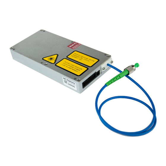
Table 3 Optical Interface Specifications Parameter SMF28 PM 1550 Fiber Mode Field Diameter ~10 microns ~10 microns Numerical Aperture 0.14 0.125 Mode field diameter is approximate - contact NKT Photonics Support contact details on Support for more information ( page 66... -
Page 23: Electrical Interfaces
Electrical Interfaces Electrical Interfaces On the front panel of the laser are two standard electrical connectors. The connectors provide the laser with electrical interfaces for: 12 VDC power • RS-485 serial communications • a safety interlock circuit • emission control (5V logic) •... -
Page 24: Main Electrical Interface
“Fast wavelength modulation input” on page Laser Control User interface The laser and any associated accessories are controlled using either NKT Photonics CONTROL Graphical User Interface (GUI) installed on a PC or the NKTP Software Development kit (SDK). If you are using the GUI, it can control the laser’s emissions and adjust its power and pulse rate settings. - Page 25 Laser Control includes multiple chapters describing the GUI and procedures related Section 2 to controlling the laser with it. Note: An optional USB to RS-485 adapter is available to connect a standard PC to the laser.
-
Page 26: Status Leds
The interlock status is Not OK – the door circuit is open or not energized. Note: the laser until you are familiar with the controls and have O NOT OPERATE taken all precautions necessary as described in the Koheras BASIK MIKRO Safety, Handling and Regulatory Information. -
Page 27: Module Labels
Module labels Module labels The Koheras BASIK MIKRO modules include multiple labels that indicate hazards, regulatory, or manufacturing information. The labels are located on several panels as described in with the top panel shown in Table 6 Figure Table 6 Module labels... - Page 28 Module labels...
-
Page 29: Operating The Laser
SECTION 2 OPERATING THE LASER This section describes how to manage and operate the laser and includes the chapters: “Communicating with the Laser” on page 31 • “Turning On the Laser” on page 35 • “Using CONTROL” on page 39 •... -
Page 31: Communicating With The Laser
PC and the laser using the optional USB to RS-485 adapter. CONTROL software The laser is shipped with the NKT Photonics CONTROL software installer on a USB key. You can also download the most recent CONTROL software from the following link: https://www.nktphotonics.com/lasers-fibers/support/software-drivers/... -
Page 32: Connecting The Laser To A Pc With Control
The laser can be managed using its RS-485 serial connection connected to a PC with CONTROL installed on it. You must use the included NKT Photonics RS-485 adapter to connect the laser to the PC’s USB port and also to a 12 VDC power source. - Page 33 Connecting the laser to a PC with CONTROL Action CONTROL automatically scans for any connect lasers and accessories available on both COM and configured Ethernet ports. CONTROL connects with the laser. In the status panel of CONTROL, the Status indicator will display AMBER until the laser thermalization set point is reached.
-
Page 34: Connecting The Laser To A Pc Using The Generic User Interface
You must use the included NKT Photonics RS-485 adapter to connect the laser to the PC’s USB port and also to a 12 VDC power source. Follow the steps in to connect the Generic User Interface to the laser. -
Page 35: Turning On The Laser
Turning on the laser will emit hazardous laser Class 3B radiation. Ensure to observe and implement all safety regulations, warnings and cautions in this guide and the Koheras BASIK MIKRO Safety, Handling and Regulatory Informa- tion document before continuing. Warning: Ensure the fiber connector face (tip) is clean. -
Page 36: Controlling The Laser Emissions
Controlling the laser emissions Controlling the laser emissions Turning On the To turn on the laser using CONTROL follow the steps in 3. To turn it on Procedure laser using the Generic User Interface use Procedure Note: The laser is equipped with internal temperature sensors that monitor the temperature of sensitive components. -
Page 37: Procedure 4 Turning On The Laser Using The Generic User Interface
Indicators Note: For a full description of the SDK, registers and the Generic User Interface, refer to the NKT Photonics document: SDK Instruction Manual. The manual is in- stalled when the SDK installer is run. - Page 38 Controlling the laser emissions...
-
Page 39: Using Control
Using CONTROL CONTROL overview The CONTROL interface includes multiple panels and a selection of menu drop down items in the upper left corner. Using the Window drop down menu, you can add or remove the displayed panels and panels can be dragged within the main window or into separate windows. -
Page 40: Relocating Panels
CONTROL overview Relocating panels The panels displayed by GUI can be dragged to other positions within the main interface or into a separate floating panel. describes how to move a Procedure 5 panel: Procedure 5 Relocating panels Action Left click hold the top title bar of a panel. While holding the left mouse button down, drag the panel to another position in the main window. -
Page 41: Toggling Panels
Status panel Toggling panels Use the Menu > Window drop down menu to check and uncheck panels to be displayed. A blue check mark indicates the panel is displayed. Figure 11 Panels dragged outside the main window Check the panels to display them Note: Clicking the X in the upper right corner of any panel will also close it. -
Page 42: Status Indicators
Status panel Figure 13 Status panel Click Status indicators The panel displays the following indicators: Interlock Indicates if power is connected to the laser. ON Green – Interlock circuit closed • ON Red – Interlock circuit open • Status Indicates the laser thermalization: ON Green –... -
Page 43: Emission Button
Status panel Emission button The Emission button turns the laser emission ON, Emissions Enabled – See “Controlling the laser emissions” on page The button indicator will turn ON RED when any laser emissions are enabled. Otherwise, it will be OFF Grey. Warning: Class 3B laser emissions will be emitted when the Emission button LED is ON RED. -
Page 44: Figure 15 Current Mode Controls
Status panel Figure 15 Current mode controls Auto-start The auto-start function can be set to operate by checking the box in this panel. Figure 16 Auto-start check box Check to enable the Auto-start function View Check the System info box to display the laser serial number and firmware release number within the status panel. -
Page 45: Control Menu Items
CONTROL menu items CONTROL menu items There are four drop down menus in the main control window as highlighted in 18. Click on the items in the menu to reveal the drop down menus. Figure Figure 18 Menu Items Menu Item Function File Exits the GUI program... -
Page 46: Application Log
CONTROL menu items Application log In addition to the Serial Monitor, the Application Log panel is used for debugging serial communications. The panel displays time stamps for both COM port open and close times and also general status information. You can clear, save and print the log data using the buttons in the upper left corner. -
Page 47: Control - Control Panel
CONTROL – Control panel CONTROL – Control panel For the Koheras BASIK MIKRO the control panel can be configured to present different operating mode controls for either Power or Current mode. The modes are selected by clicking on the Settings drop down menu (gear icon) in the status panel. - Page 48 CONTROL – Control panel...
-
Page 49: Software Development Kit
Note: For a full description of the SDK, registers and the Generic User Interface, refer to the NKT Photonics document: SDK Instruction Manual. The manual is in- stalled along with the SDK components when the SDK installer is run. Tuning the wavelength The relationship between temperature and the fiber laser’s wavelength is stored... -
Page 50: Setting The Operating Mode
Setting the operating mode Setting the operating mode To set the operating mode modify bit 8 of register 0x31. When the bit is set to ‘0’ Power mode is selected and when set to ‘1’, ‘Current mode’ is selected. Figure 24 Setting register 0x31 – setup bits (operating mode) To set the mode input the following examples into register 0x31: 001F –... -
Page 51: Setting The Emission Delay
Setting the emission delay 005F – auto-start function is enabled with current mode set • 004F – auto-start function is enabled with power mode set • 001F – auto-start function is disabled with current mode set • Warning: 000F – auto-start function is disabled with power mode set Note: For register 31, bits 0-7 and bits 9, 11-15 are unused. - Page 52 Setting the emission delay...
-
Page 53: Installing The Laser
SECTION 3 INSTALLING THE LASER This section describes how to install the laser and includes the chapters: “Mechanical Installation” on page 55 • “Connecting the laser” on page 57 •... -
Page 55: Mechanical Installation
Mechanical Installation The Koheras BASIK MIKRO is designed to be used as a stand-alone module installed on a flat surface. The laser generates a substantial amount of heat that must be dissipated. This section describes how to mount the laser module to ensure optimal function. -
Page 56: Operating And Storage Environment
Warning: The Koheras BASIK MIKRO is a Class 3B laser product and its operation facility and conditions must comply with the standards listed below or similar: CFR21 1040.10 & Laser Notice LN50 • IEC / EN 60825-1... -
Page 57: Connecting The Laser
Connecting the laser Before operating the laser, follow the procedures in this chapter to ensure its correct and safe operation. For information on how to connect: The Safety Interlock – see “Connecting the safety interlock” on page 57 • Power – see “Connecting power”... -
Page 58: Connecting An Interlock Switch
Caution: Do not short-circuit the Interlock input. Short-circuiting the interlock cir- cumvents safety regulations and NKT Photonics does not take liability for any in- juries or damage caused by doing so. Caution: The switch connected to the interlock must be of an approved type. Fur- ther, the switch must be installed in a manner so that its operation cannot be fixed in the open state using a tool. -
Page 59: Connecting Power
Connecting power Connecting power The RS-485 adapter kit includes an external power supply shown in 29. . Figure The power supply connects its 12 volts DC output to the RS-485 adapter by means of a two pole barrel connector. Power is delivered to the laser through the ribbon cable from the adapter to the laser’s 16 pin main interface connector. -
Page 60: Slew Rate
Before connecting the optical output connector (FC/APC), ensure to check the connector tip using a fiber microscope. Using the microscope, check for any deformities, damage, residue or other contaminants at the optical tip of the connector. Either clean the connector or contact NKT Photonics support if replacement is necessary. -
Page 61: Appendices
APPENDICES The appendices include: Specifications Appendix A on page 63 • Service and support Appendix B on page 65 • Interface pin assignments Appendix C on page 67 • CONTROL Installation Appendix D on page 69 • RS-485 Adapter Appendix E on page 75 •... -
Page 63: A Specifications
Specifications Table 10 Optical CW - inherently single frequency CW - inherently single frequency Laser Emission < 1.05 < 1.05 Beam Quality (M2) < 0.1 < 15 Linewidth (kHz) -90@10 Hz -69@10 Hz Max. Phase Noise (µrad/√Hz/m) -110@100 Hz -89@100 Hz -130@20 kHz -109@20 kHz 32@10 Hz... -
Page 64: Table 13 Electrical
Table 13 Electrical All Chassis Models Supply Voltage 11 to 13 VDC 5 A 10 W Maximum Power Consumption Table 14 Safety and regulatory compliances Safety Regulatory EN 60825-1:2014: Safety of laser products EN 61326-1:2013: Electrical equipment for measurement, Part 1: Equipment classification and requirements control and laboratory use EMC requirements –... -
Page 65: B Service And Support Information
Service and support Information Servicing the laser The laser have no user serviceable components. In case of malfunction, contact NKT Photonics using the support channels in section “Support contact details”. Caution: Do not open the laser’s modules. The laser modules are equipped with warranty labels (see 31) on the covers of the laser chassis. -
Page 66: Support Contact Details
Support contact details Support contact details For technical or general support, NKT Photonics can be contacted for help regarding issues and questions with your laser or its accessories. Support Email support@nktphotonics.com Online support http://www.nktphotonics.com (click on support) web-page Shipping address... -
Page 67: C Interface Pin Assignments
Emission Collector output with internal 240 Ω resistor in series. High when the Koheras BASIK MIKRO has laser emission ON. Anode from a LED can be connected directly to this pin and the Cathode to GND to indicate laser emission externally. - Page 68 Fast wavelength modulation input...
-
Page 69: D Control Installation
CONTROL installation Installing CONTROL Download the software from: https://www.nktphotonics.com/lasers-fibers/support/software-drivers/ Follow the steps in Procedure Procedure 7 Installing CONTROL Action On the PC, launch the installer package and then click the Installer Run button. The installation wizard appears. Click Next to continue. - Page 70 Installing CONTROL Action Accept to use the default installation directory or select another directory by clicking the Browse button. Click Next to continue. Uncheck the components you do not require. By default, all components will be installed. Click Next to continue. Read the End-User License Agreement, and select: “I accept the license.”.
- Page 71 Installing CONTROL Action The wizard will create a start menu folder with program short-cuts. Use the default name or enter a new name for the folder. Click Next to continue. Check the box to create a desktop shortcut to access Control.
- Page 72 Installing CONTROL Action Click Install to install NKTP Control software on your PC. Click Cancel if you want to abort the installation. The wizard displays a progress meter for the installation. Note: a normal install should only take a few seconds. Click Next to install the UART drivers for the PC USB port.
- Page 73 Installing CONTROL Action The drivers will be installed. The Silicon Labs drivers is installed successfully. Click Finish to end the installation wizard. CONTROL is now installed. Check the Run box to launch CONTROL when the Finish button is clicked. Click Finish.
- Page 74 Installing CONTROL...
-
Page 75: E Rs-485 Adapter
Interlock connections and defeater (jumper) • Status LEDs • If you need an adapter and its associated components contact NKT Photonics support, see “Support contact details” on page Main adapter depicts the adapter port interfaces that connect to both the PC and Figure 32 laser. -
Page 76: Figure 32 Rs-485 Adapter
Figure 32 RS-485 adapter PC-Side Laser Side 2-pin LEMO interlock connector 4 12 VDC power input USB type B connector 5 Interlock defeater (jumper) Status LEDs 6 DB-15 laser interface – see Main electrical interfaces on page 67... -
Page 77: F Configuration Id
Configuration ID BASIK MIKRO modules are available as either C15 or E15 variants (see Table 1 on 18). The modules can be specified with various options that are indicated in page the six fields of the module configuration ID shown in 33. - Page 79 Koheras BASIK MIKRO Product Description Revision 1.1 01-2020 W-10456...
Need help?
Do you have a question about the Koheras BASIK MIKRO and is the answer not in the manual?
Questions and answers