Sign In
Upload
Manuals
Brands
NKT Manuals
Control Unit
Koheras BASIK MIKRO
NKT Koheras BASIK MIKRO Fiber Laser Manuals
Manuals and User Guides for NKT Koheras BASIK MIKRO Fiber Laser. We have
1
NKT Koheras BASIK MIKRO Fiber Laser manual available for free PDF download: Product Manual
NKT Koheras BASIK MIKRO Product Manual (79 pages)
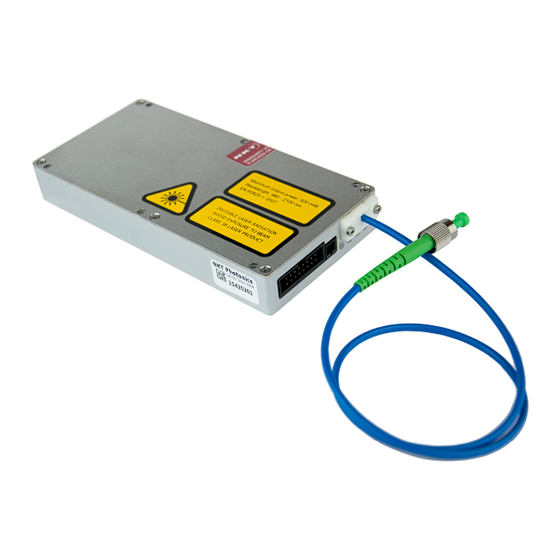
Low Noise Single Frequency Laser Module
Brand:
NKT
| Category:
Control Unit
| Size: 11.63 MB
Table of Contents
Guide Overview
3
Terminology
3
Table of Contents
5
Contents
5
Tables
9
Figures
11
Procedures
13
Basik Mikro Description
15
1 Laser Description
17
Theory of Operation
17
Figure 1 Working Panel of the BASIK MIKRO
17
Module Variants
18
Configuration ID
18
Center Wavelength
18
Tuning Types
18
Laser Features
18
Thermal Tuning
18
Table 1 BASIK MIKRO Output Specifications
18
Fast Wavelength Modulation
19
Operating Mode
19
Figure 2 Frequency Response Using Wavelength Modulation
19
Auto-Start
20
Emission Delay
20
Shutdown Delay
20
High Temperature Shutdown
20
Table 2 Recommended Power Modes
20
Power Verification
21
Miscellaneous
21
Power Supply
21
Safety
21
Accessories
21
Optical Interface
22
Table 3 Optical Interface Specifications
22
Figure 3 USB-RS485 Adapter
22
Figure 4 BASIK MIKRO Equipped with Fiber Cord and FC/APC Connector
22
Electrical Interfaces
23
Figure 5 Front Panel Electrical Connections
23
Table 4 Connectors
23
Fast Wavelength Modulation Input
24
Main Electrical Interface
24
Laser Control
24
User Interface
24
Status Leds
26
Table 5 Status Leds
26
Figure 6 Status Leds
26
Module Labels
27
Table 6 Module Labels
27
Figure 7 Top Panel Label Locations
27
Operating the Laser
29
2 Communicating with the Laser
31
CONTROL Software
31
Installing the Software
31
Software Development Kit
31
Generic User Interface
31
Connecting the Laser to a PC with CONTROL
32
Procedure 1 Connecting CONTROL to the Laser
32
Connecting the Laser to a PC Using the Generic User Interface
34
Procedure 2 Connecting the Generic User Interface to the Laser
34
3 Turning on the Laser
35
Safety
35
Preparation
35
Controlling the Laser Emissions
36
Turning on the Laser
36
Procedure 3 Turning on the Laser Using CONTROL
36
Procedure 4 Turning on the Laser Using the Generic User Interface
37
4 Using CONTROL
39
CONTROL Overview
39
Figure 8 GUI Panel Navigation
39
Table 7 CONTROL Panels and Menu Items
39
Figure 10 Panels Dragged Outside the Main Window
40
Figure 9 Panel Dragged to a New Location in the Main Window
40
Procedure 5 Relocating Panels
40
Relocating Panels
40
Connecting to the Laser
41
Toggling Panels
41
Status Panel
41
Figure 11 Panels Dragged Outside the Main Window
41
Figure 12 Welcome Screen and Connecting
41
Figure 13 Status Panel
42
Status Indicators
42
System Info
42
CONTROL Settings
43
Emission Button
43
Figure 14 GUI Settings
43
Figure 15 Current Mode Controls
44
Figure 16 Auto-Start Check Box
44
Figure 17 View Setting
44
CONTROL Menu Items
45
Serial Monitor
45
Figure 18 Menu Items
45
Figure 19 Serial Monitor
45
Application Log
46
Figure 20 Serial Monitor
46
CONTROL - Control Panel
47
Power Mode
47
Current Mode
47
Figure 21 Operating Mode Set to Power
47
Figure 22 Operating Mode Set to Power
47
5 Software Development Kit
49
Tuning the Wavelength
49
Figure 23 Setting Register 0X2A - Wavelength
49
Setting the Operating Mode
50
Auto Start
50
Figure 24 Setting Register 0X31 - Setup Bits (Operating Mode)
50
Figure 25 Setting Register 0X31 - Setup Bits (Auto-Start Function)
50
Setting the Emission Delay
51
Figure 26 Setting Register 0X3A - Emission Delay
51
Installing the Laser
53
6 Mechanical Installation
55
General
55
Heat Dissipation
55
Installation Method
55
Operating and Storage Environment
56
Figure 27 Mounting the Laser
56
7 Connecting the Laser
57
Connecting the Safety Interlock
57
Interlock Operation
57
LEMO Connector
57
Connecting an Interlock Switch
58
Figure 28 IRS-485 Adapter Connected to a Door Switch (Open Position)
58
Procedure 6 Connecting the Door Interlock Circuit
58
Connecting Power
59
Fast Wavelength Modulation Input
59
Figure 29 Power Supply
59
Table 8 Power Adapter Specifications
59
Slew Rate
60
Connecting the Optical Output
60
Table 9 Fast Wavelength Modulation Specifications
60
Appendices
61
A Specifications
63
Table 10 Optical
63
Table 11 Mechanical Dimensions
63
Table 12 Operating and Storage Environment
63
Table 13 Electrical
64
Table 14 Safety and Regulatory Compliances
64
Figure 30 Mechanical Dimensions
64
B Service and Support Information
65
Servicing the Laser
65
Opening the Laser Chassis
65
WARRANTY VOID if REMOVED Label
65
Figure 31 Warranty Seal
65
Support Contact Details
66
Support Email
66
Online Support Web-Page
66
Shipping Address
66
C Interface Pin Assignments
67
Main Electrical Interfaces
67
Fast Wavelength Modulation Input
67
Table 15 Main Electrical Interface Pin Assignment
67
Table 16 Fast Wavelength Modulation Input
67
D CONTROL Installation
69
Installing CONTROL
69
Procedure 7 Installing CONTROL
69
E RS-485 Adapter
75
Main Adapter
75
Table 17 RS-485 Adapter Status Leds
75
Figure 32 RS-485 Adapter
76
F Configuration ID
77
Module Configuration ID
77
Table 18 Standard BASIK MIKRO Configuration Ids
77
Figure 33 How to Read the Configuration ID
77
Advertisement
Advertisement
Related Products
NKT Koheras BASIK
NKT Categories
Measuring Instruments
Control Unit
Cables and connectors
Lighting Equipment
Amplifier
More NKT Manuals
Login
Sign In
OR
Sign in with Facebook
Sign in with Google
Upload manual
Upload from disk
Upload from URL