Table of Contents
Advertisement
Quick Links
Advertisement
Table of Contents

Related Manuals for NKT Koheras BASIK

Summary of Contents for NKT Koheras BASIK
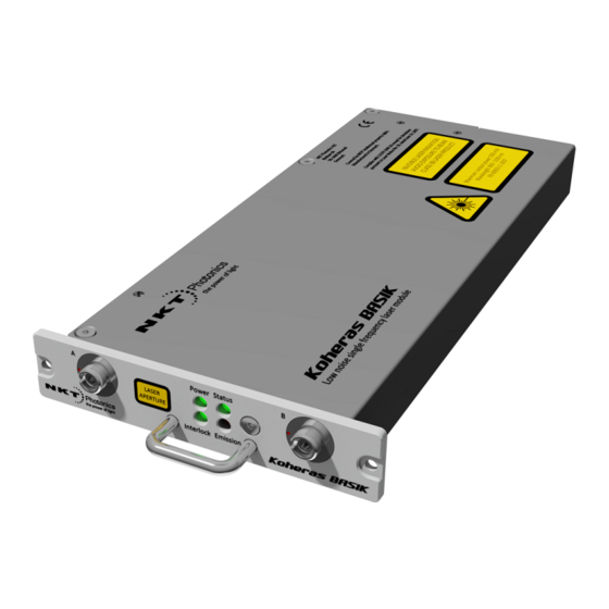
- Page 1 Koheras BASIK Low Noise Single Frequency Laser Module PRODUCT GUIDE...
- Page 2 PRODUCT GUIDE This guide includes the following NKT Photonics Lasers: Koheras BASIK Low Noise Single Frequency Laser Module Koheras BASIK Product Description Revision 1.1 01-2020 W-10456...
-
Page 3: Guide Overview
Terminology This guide may refer to the Koheras BASIK modules as “the laser”. In specific cases where a distinction is required, this guide will use the actual laser model names or simply refer to the laser as the “module”. - Page 4 Note: Highlights additional information related to the associated topic and/or provides links or the name of the NKT guides describing the additional informa- tion. Caution: Alerts you to a potential hazard that could cause loss of data, or damage the system or equipment.
-
Page 5: Table Of Contents
Guide Overview ........................3 Terminology ......................3 TABLES ........................11 FIGURES ........................13 PROCEDURES ......................17 Section 1 KOHERAS BASIK DESCRIPTION 1 Laser Description .......................21 Features and Options ..................21 Theory of operation ................... 22 Module variants ......................22 Configuration ID ....................22 Center wavelength ..................... - Page 6 High temperature shutdown ................28 Power verification ....................28 Miscellaneous ......................29 Power supply ....................... 29 Safety ........................29 Accessories ......................29 Optical interface ......................30 Optical fibers, connectors and adapters ............30 Laser Control ......................31 User interface ....................... 31 Status LEDs .........................
- Page 7 Installing the software ..................47 Software Development Kit ..................48 Generic User Interface ..................48 Connecting the laser to a PC with CONTROL ..........48 Connecting the laser to a PC using the Generic User Interface ....51 4 Turning ON the Laser .......................53 Safety ...........................
- Page 8 CONTROL – Control panel ..................71 Wavelength ......................71 Power mode ......................71 Current mode ....................... 72 6 Software Development Kit ....................73 Read/write registers ....................74 Tuning the wavelength ..................74 Setting the operating mode ................74 Auto start ........................74 Setting the emission delay ................75 Narrow and wide range setting ..............
- Page 9 Heat dissipation ....................87 Slide-in mounting ..................... 88 Operating and storage environment ............. 90 8 Connecting the Laser ......................91 Connecting the safety interlock ................91 Interlock operation ....................91 Lemo connector ....................91 Connecting an interlock switch ..............92 Connecting power ....................93 Connecting modulation signals ................
- Page 10 E RS-485 adapter .........................115 Main adapter ......................115 F Configuration ID ....................... 117 Module Configuration ID ................... 117...
-
Page 11: Tables
Table 5: Module labels......................33 Table 6: Wavelength modulation settings ..............36 Table 7: Narrow vs wide band wavelength modulation..........40 Table 8: Koheras BASIK PC connection kit ..............47 Table 9: CONTROL panels and menu items ..............57 Table 10: Generic user interface registers ..............73 Table 11: Power adapter specifications................ -
Page 13: Figures
FIGURES Figure 1: BASIK front panel ....................21 Figure 2: BASIK front panel layout .................. 24 Figure 3: BASIK rear panel layout ................... 25 Figure 4: Frequency response using wavelength modulation ........ 26 Figure 5: USB-RS485 Adapter ..................29 Figure 6: BASIK equipped with fiber cord and FC/APC connector ....... 30 Figure 7: Status LEDs ...................... - Page 14 Figure 29: Wavelength modulation - both ..............64 Figure 30: Internal generator waveform selection (Type) ........64 Figure 31: Turning on wavelength modulation ............66 Figure 32: Trigger type – Input ..................67 Figure 33: Trigger type – Output ..................67 Figure 34: Power &...
- Page 15 Figure 60: Heat transfer surface - BASIK rear panel ..........87 Figure 61: Heat transfer surface - BASIK rear panel ........... 88 Figure 62: Mounting the laser ..................89 Figure 63: Front panel mounting holes and handle ........... 90 Figure 64: Safety interlock connected to a door switch (open position) ....92 Figure 65: Power supply ....................
-
Page 17: Procedures
PROCEDURES Procedure 1: Connecting CONTROL to the laser............49 Procedure 2: Connecting the Generic User Interface to the laser......51 Procedure 3: Turning on the laser using CONTROL..........54 Procedure 4: Turning on the Laser using the Generic User Interface ....55 Procedure 5: Relocating panels .................. -
Page 19: Koheras Basik Description
SECTION 1 KOHERAS BASIK DESCRIPTION This section provides a description of the laser and its chassis types. It includes the following topics: “Laser Description” on page 21 • “Module variants” on page 22 • “Main electrical Interface” on page 24 •... -
Page 21: Laser Description
Laser Description Koheras BASIK is a single frequency distributed feedback (DFB) fiber laser system housed in a robust package with passive vibration reduction. The laser is available as single laser or as a building block used for example in multi channel DWDM systems. -
Page 22: Theory Of Operation
Module variants The Koheras BASIK modules are available in four variants. The modules are mainly classified by their wavelength and output power. describes the Table 1 primary technical differences between the variants. -
Page 23: Output Power
Front and rear panels Output power Depending on the module type, the output power varies between greater than 10 mW and up to and including 40 mW. The output power is fixed for the lasers. Tuning types The laser’s variants can be further specified with different tuning options. The options include narrow and wide thermal tuning for coarse adjustment and Piezo tuning for finer adjustment. -
Page 24: Rear Panel
Front and rear panels For more information see “Status LEDs” on page Figure 2 BASIK front panel layout Status LEDs Optical output A Handle Optical output B (SC/APC option) (SC/APC option) Directly underneath the status LEDs there is, a handle. Use the handle for pulling the laser out from a slot mount (such as the Koheras ACOUSTIC). -
Page 25: Optical Specifications
Optical specifications The pin assignments of the connector are described in Appendix Figure 3 BASIK rear panel layout M4 screw hole M4 screw hole Alignment hole Main electrical interface (used with an external post) (DIN 30 pin C/3 - male) Alignment and tapped holes If the laser is inserted into a slot assembly, the alignment hole on the rear panel is designed to slide onto an alignment post on the associated housing. -
Page 26: Fast Wavelength Modulation
Laser features under tension on a substrate. When the temperature of the substrate changes, the laser cavity length also changes due to thermal contraction or expansion. Further, the temperature of the laser cavity itself also changes such that the laser wavelength changes in response to both thermo-optic and physical changes in the optical path length. -
Page 27: External Cavity Stabilization
Laser features External cavity X15 modules support the use of the Pound-Hall-Drever technique to reduce low stabilization frequency phase noise to an ultra-low level. It requires that the X15 output is stabilized using an external cavity circuit. Refer to “External cavity stabilization for details of the implementation. -
Page 28: Emission Delay
Laser features Koheras ADJUSTIK & ACOUSTIK If the module is used within either the ADJUSTIK or ACOUSTIK chassis, auto-start is overruled and cannot start laser emissions even if the auto-start bit is set. KeyUpdater To enable/disable the Auto-Start feature, use the KeyUpdater tool with either key below. -
Page 29: Miscellaneous
An external 12 VDC power source is required (not included with the laser). Power is connected to the main electrical interface connector, see “Main electrical Interface” on page The NKT Photonics RS-485 adapter kit includes a power supply for the laser. See – “Accessories” “USB-RS485 adapter kit”. -
Page 30: Optical Interface
• – or – connector adapters (FC/APC adapter or SC/APC adapter) • shows a Koheras BASIK assigned with a fiber patch cable and FC/APC Figure 6 connector assigned to optical port A as the main output. 2, shows the front Figure panel layout when both optical ports are assigned as SC/APC adapters. -
Page 31: Laser Control
106). Laser Control User interface The laser and any associated accessories are controlled using either NKT Photonics CONTROL Graphical User Interface (GUI) installed on a PC or the NKTP Software Development kit (SDK). If you are using the SDK GUI, it can control the laser’s emissions and adjust its power and wavelength settings. -
Page 32: Module Labels
Note: the laser until you are familiar with the controls and have O NOT OPERATE taken all precautions necessary as described in the document: Koheras BASIK Safety, Handling and Regulatory Information. Module labels The Koheras BASIK modules include multiple labels that indicate hazards, regulatory, or manufacturing information. -
Page 33: Table 5 Module Labels
Module labels Figure 9 Front panel label locations Table 5 Module labels Label Panel Description Classification - Safety information stating the laser Emission emission hazards and the laser’s class Hazards rating. Manufacturing Side Manufacturing information including address, part and serial number, date manufactured and regulatory compliance. - Page 34 Module labels...
-
Page 35: Modulation
Configuring The wavelength of the Koheras BASIK module can be modulated with either: external and internal wavelength an external electrical signal applied to the Wavelength+/- input, •... -
Page 36: Wavelength+/- Signal
Fast wavelength modulation Table 6 Wavelength modulation settings Setting Function For CONTROL see For SDK see External wavelength Sets wavelength page 62 page 76 modulation modulation to external signal mode. Internal function Sets wavelength page 64 page 76 generator modulation to internal function generator mode. -
Page 37: Differential Input
Fast wavelength modulation Differential input When configured as an input, the Wavelength+/- interface can be connected to a differential signal with an amplitude up to 2x 5 Vpp as shown in Figure Figure 10 Differential input signal for wavelength modulation Note: To prevent noise being induced that could create undesired phase noise, it is recommended to disable the wavelength modulation setting when it is not in... -
Page 38: Figure 12: Single-Ended Input Signal With 2.5 V
Fast wavelength modulation 2.5 V or GND. A single-ended 5 Vpp signal generates half the modulation compared to a differential 2x5 Vpp input. Figure 12 Single-ended input signal with 2.5 V shows the Wavelength- pin connected to the same potential as the Figure 13 common mode voltage of the Wavelength+ signal, the optical output will be modulated around its center wavelength. -
Page 39: Wavelength- To Gnd
Fast wavelength modulation Wavelength- to 15, the Wavelength- signal is connected to GND and the Wavelength+ Figure signal is modulated between 0 and 5 V as shown in 14, the optical output Figure is modulated above its thermally controlled wavelength. Figure 14 Single-ended input signal with GND on an unused branch Figure 15 Single-ended input connections with 0 V on an unused branch... -
Page 40: Differential Output
1.6 Hz. Setting the Koheras BASIK X15 to DC coupling allows the laser to lock coupling to an external reference signal that for example, uses the Pound Drever Hall technique. -
Page 41: Figure 17 Basik X15 Wavelength Modulation Response
Fast wavelength modulation (E15/C15/Y10) shows the response when the modulation signal varies Figure 18 from 1 to 100 kHz. X15 frequency response shows the measured frequency response of the BASIK X15 for both Figure 17 wide and narrow ranges: Wide – 500 MHz tuning at low frequencies with a smooth roll-off to a 3 dB •... -
Page 42: External Cavity Stabilization (Basik X15)
External cavity stabilization (BASIK X15) Narrow – 10x (times) less with a 3 dB cut-off at 1 kHz • Figure 18 BASIK E15/C15/Y10 wavelength modulation response External cavity stabilization (BASIK X15) An X15 module can be locked to an external cavity to obtain lower low-frequency phase noise by using the Pound-Drever-Hall technique. -
Page 43: Setting Up External Cavity Stabilization
External cavity stabilization (BASIK X15) Setting up external Follow the steps below to configure and enable external cavity locking: cavity stabilization Enable external modulation (see “Modulation Source” on page 62). 2. Configure the wavelength modulation input as DC coupled (see “Modulation Coupling”... - Page 44 External cavity stabilization (BASIK X15)
-
Page 45: Operating The Laser
SECTION 2 OPERATING THE LASER This section describes how to manage and operate the laser and includes the chapters: “Communicating with the Laser” on page 47 • “Turning ON the Laser” on page 53 • “Using CONTROL” on page 57 •... -
Page 47: Communicating With The Laser
15 A power cord C7 to EU/US/UK USB cable – Type A to B CONTROL software The laser is shipped with the NKT Photonics CONTROL software installer on a USB key. You can also download the most recent CONTROL software from the following link: https://www.nktphotonics.com/lasers-fibers/support/software-drivers/... -
Page 48: Software Development Kit
Software Development Kit Software Development Kit NKT Photonics provides an SDK for use when integrating the laser with your custom control system. You can download the SDK from the same URL where CONTROL installer is found: https://www.nktphotonics.com/lasers-fibers/support/software-drivers/ To install the SDK, run the installer and follow the instructions in the install wizard. -
Page 49: Procedure 1 Connecting Control To The Laser
Figure Launch CONTROL by either: • clicking on Windows – Start – Programs – NKT Photonics – CONTROL – or – • double clicking the CONTROL shortcut on the desktop The CONTROL window opens. - Page 50 Connecting the laser to a PC with CONTROL Action CONTROL connects with the laser. In the statuXs panel of CONTROL, the Status indicator is AMBER. The indicator turns GREEN when the laser thermalization set point is reached. END CONTROL connection Procedure...
-
Page 51: Connecting The Laser To A Pc Using The Generic User Interface
SDK installed on it. The SDK provides a Generic User Interface that can read and write registers in the laser module. You can use the NKT Photonics RS- 485 adapter to connect the laser to the PC’s USB port and also to a 12 VDC power source. - Page 52 Connecting the laser to a PC using the Generic User Interface Action 4 The Generic User Interface connects to the laser and displays the current register values.
-
Page 53: Turning On The Laser
Warning: Turning on the laser will emit hazardous laser Class 3B radiation. Ensure to observe and implement all safety regulations, warnings and cautions in this guide and the Koheras BASIK Safety, Handling and Regulatory Information docu- ment before continuing. Warning: Ensure the fiber connector face (tip) is clean. -
Page 54: Controlling The Laser Emissions
Controlling the laser emissions Controlling the laser emissions Turning On the To turn on the laser using CONTROL follow the steps in 3. To turn it on Procedure laser using the Generic User Interface use Procedure Note: The laser is equipped with internal temperature sensors that monitor the temperature of sensitive components. -
Page 55: Procedure 4 Turning On The Laser Using The Generic User Interface
Indicators Note: For a full description of the SDK, registers and the Generic User Interface, refer to the NKT Photonics document: SDK Instruction Manual. The manual is in- stalled when the SDK installer is run. - Page 56 Controlling the laser emissions...
-
Page 57: Using Control
Using CONTROL CONTROL overview The CONTROL interface includes multiple panels and a selection of menu drop down items in the upper left corner. Using the Window drop down menu, you can add or remove the displayed panels and panels can be dragged within the main window or into separate windows. -
Page 58: Relocating Panels
CONTROL overview Relocating panels The panels displayed by GUI can be dragged to other positions within the main interface or into a separate floating panel. Procedure 5 describes how to move a panel: Procedure 5 Relocating panels Action Left click hold the top title bar of a panel. While holding the left mouse button down, drag the panel to another position in the main window. -
Page 59: Toggling Panels
Status panel Toggling panels Use the Menu > Window drop down menu to check and uncheck panels to be displayed. A blue check mark indicates the panel is displayed. Figure 23 Panels dragged outside the main window Check the panels to display them Note: To close a panel, click the X at the upper right corner of the panel... -
Page 60: Status Indicators
Status panel Figure 25 Status panel Click Status indicators The panel displays the following indicators: Interlock Indicates if power is connected to the laser. ON Green – Interlock circuit closed • ON Red – Interlock circuit open • Status Indicates the laser thermalization: ON Green –... -
Page 61: Module Info
CONTROL settings Module info The System Info section shows the following: Laser serial number • Laser firmware revision • Measurements Displays the system temperature. WL mod button and Button indicator The WL mod button turns the wavelength modulation ON or OFF. Indicator GREEN –... -
Page 62: Wavelength Modulation
CONTROL settings Figure 26 GUI settings Click the gear icon to access the menu Setting Item Function Wavelength Toggles the mode of the laser between power Wavelength modulation on modulation and current mode. page 62 Trigger Configures the trigger pin behaviour Trigger on page 66 Power/current Check box to toggle Auto-start on or off. -
Page 63: Figure 27 Wavelength Modulation - Internal Source
CONTROL settings Figure 27 Wavelength modulation - internal source Figure 28 Wavelength modulation - external source... -
Page 64: Figure 29 Wavelength Modulation - Both
CONTROL settings Figure 29 Wavelength modulation - both Modulation Type (internal mode) If the Modulation source is set to Internal, you can set the signal waveform type that is generated internally. Click the Type drop-down menu arrow and select either Sinusoidal, Triangle, Sawtooth or an Inverse sawtooth waveform. Figure 30 Internal generator waveform selection (Type) Modulation Coupling You can select to couple the modulation signal using either AC or DC coupling. - Page 65 CONTROL settings When set to “Narrow”, modulation depth is limited but the X15’s low phase noise is maintained. To increase the modulation depth, change the range setting to “Wide”. When the modulation range is set to “Wide”, phase noise will increase. Note: Refer to “Narrow vs.
-
Page 66: Trigger
CONTROL settings Figure 31 Turning on wavelength modulation Click to enable wavelength modulation Trigger The trigger function can be used to either initiate emission using an input logic trigger signal or output a logic trigger signal when emission in enabled. The trigger signal output or input is connected to pin B4 of the main electrical interface (see Table... -
Page 67: Power/Current Mode
CONTROL settings Figure 32 Trigger type – Input Figure 33 Trigger type – Output Power/Current The laser output controls can be set to either Power or Current mode as mode described in “Operating mode” on page 27. Click the menu item shown in Figure 34 to toggle the mode. -
Page 68: Auto-Start
CONTROL settings Figure 34 Power & current mode controls Auto-start Check the System info box to display the laser serial number, firmware release number or system temperature within the status panel. Figure 35 Auto-start setting When checked, laser emission is enabled on connecting power View Check the System info box to display the laser serial number, firmware release number or system temperature within the status panel. -
Page 69: Control Menu Items
CONTROL menu items CONTROL menu items There are four drop down menus in the main control window as highlighted in Figure 37. Click on the items in the menu to reveal the drop down menus. Figure 37 Menu items Menu Item Function File Exits the GUI program... -
Page 70: Figure 39 Serial Monitor
CONTROL menu items and close times and also general status information. You can clear, save and print the log data using the buttons in the upper left corner. Figure 39 Serial Monitor Clear the log Save the log to file Print the log The panel is enabled by placing a check mark on the Window pull down menu next to the Application Log item. -
Page 71: Control - Control Panel
CONTROL – Control panel CONTROL – Control panel For the Koheras BASIK the control panel can be configured to present different operating mode controls for either Power or Current mode. The modes are selected by clicking on the Settings drop down menu (gear icon) in the status panel. -
Page 72: Current Mode
CONTROL – Control panel Current mode In the Current operating mode the current in the fiber pump is kept at a constant level. Only the wavelength offset (or wavelength) control is available in the control panel menu. Operating Mode set to Power The wavelength offset can be manually entered... -
Page 73: Software Development Kit
81 Note: For a full description of the SDK, registers and the Generic User Interface, refer to the NKT Photonics document: SDK Instruction Manual. The manual is in- stalled when the SDK installer is run. -
Page 74: Read/Write Registers
Figure 42 Setting the wavelength offset Input the wavelength offset in picometers into the register field and press enter. Contact NKT Photonics support for the range settable. Setting the To set the operating mode modify bit 9 of register 0x31. When the bit is set to ‘0’... -
Page 75: Setting The Emission Delay
Read/write registers Figure 44 Setting the auto-start function Setting the To set the emission delay timer use register 0x3A. Input the time in seconds into emission delay the register. Figure 45 Setting the emission delay Narrow and wide To alternate between Wide and Narrow range setting, set bit 3 of register 0x31, range setting where ‘0’... -
Page 76: Setting The Wavelength Modulation Source
Read/write registers Figure 46 Setting the range parameter Setting the To set the signal source for the wavelength modulation option, use bit 5 of wavelength register 0x31. Setting the bit to 0 sets wavelength modulation to use an external signal and 1 means to use the internal generator signal. To set the source to use modulation source both external and internal signals (both), set bits 5 and 4 of 0x31 to 1. -
Page 77: Setting The Wavelength Modulation Signal Coupling
Read/write registers Both • 0x31 set to 0514 – both (internal & external) - wide range • 0x31 set to 0516 – both (internal & external) - narrow range • Setting the To set the signal coupling for the wavelength modulation option, use bit 4 of wavelength register 0x31. -
Page 78: Internal Generator Frequency
Read/write registers Internal generator Internal function generator frequency is set with register 0xB8.0. The value is set frequency with a 32-bit float value in hertz with a range from 0.008 to 100,000 Hz. Figure 49 Setting the internal generator frequency Internal generator The amplitude of the internal function generator signal is set with register 0x2B. -
Page 79: Internal Generator -Signal Output
Read/write registers 01 – sinusoidal • 41 - triangular • 81 – sawtooth • C1 – inverse sawtooth • Figure 51 Setting the internal generator waveform Internal generator - To enable or disable outputting the internal generator signal on the Wavelength signal output +/- pins use bit 6 of register 0x31, where setting the bit to ‘0’... -
Page 80: Wavelength Modulation On/Off
Read/write registers Wavelength To turn on Wavelength modulation set register 0xB5, where ‘0’ means ‘OFF’ and modulation on/off ‘1’ means ‘ON’. Figure 53 Turning ON wavelength modulation Trigger setting To set the Trigger signal pin to be used as input or output use register 0xB4 bit 1, input/output where ‘0’... -
Page 81: Trigger Indicates Emission
Read/write registers Trigger indicates To configure the Trigger signal to indicate laser emission is enabled set bit 4 of emission register 0xB4, where ‘1’ means ‘Emission’ and ‘0’ means OFF which results in no signal being sent even if the laser emission is enabled. Note: Bit 4 cannot be set simultaneously with bit 2 of register 0xB4. -
Page 82: Readings
Readings Readings For each module, click on the Readings tab to view the contents of read-only registers. Of particular interest are registers 17 and 90. When laser emission is enabled, the output power in mW and dBm is displayed in these registers respectively. -
Page 83: Errors And Status Indicators
Status indicators The status indicators will be lit green if the condition in the text is true. Error codes If an error code is listed and cannot be cleared contact NKT Photonics support, “Support contact details” on page 106. Figure 58 Error and status tab... -
Page 84: Figure 59 Graphing Tab
Graphing Figure 59 Graphing tab Y-axis settings X-axis... -
Page 85: Installing The Laser
SECTION 3 INSTALLING THE LASER This section describes how to install the laser and includes the chapters: “Mechanical Installation” on page 87 • “Connecting the Laser” on page 91 •... -
Page 87: Mechanical Installation
Mechanical Installation The laser module is designed to be used as either a stand-alone module installed on a flat surface or as a sub-module which can be slid into a shelf or other appropriate receptacle. The laser generates heat that must be dissipated. This section describes how to mount the laser module to ensure optimal function and heat dissipation. -
Page 88: Slide-In Mounting
Slide-in mounting Thermal resistance Thermal resistance (R ) to the environment depends on the maximum θ environmental temperature. The maximum module temperature and maximum power consumption for the module is calculated as follows: = (t – t ) / P θ... -
Page 89: Figure 62 Mounting The Laser
Slide-in mounting Heat dissipation Ensure that when the laser is slid in place, the rear heat dissipation area (see 87) makes contact with a suitable surface that can “Heat dissipation” on page conduct heat away from the laser. Aligning the main electrical interface shows a 3.3 mm alignment hole with a depth of 8 mm available in the Figure 61 center of the heat transfer surface. -
Page 90: Operating And Storage Environment
Appendix A storage specifications. environment Warning: The Koheras BASIK is a Class 3B laser product and its operation facility and conditions must comply with the standards listed below or similar: CFR21 1040.10 & Laser Notice LN50 • IEC / EN 60825-1... -
Page 91: Connecting The Laser
Connecting the Laser Before operating the laser, follow the procedures in this chapter to ensure its correct and safe operation. For information on how to connect: The Safety Interlock – see “Connecting the safety interlock” on page 91 • Power – see “Connecting power”... -
Page 92: Connecting An Interlock Switch
Caution: Do not short-circuit the Interlock input. Short-circuiting the interlock cir- cumvents safety regulations and NKT Photonics does not take liability for any in- juries or damage caused by doing so. Caution: The switch connected to the interlock must be of an approved type. -
Page 93: Connecting Power
Connecting power Connecting power The RS-485 adapter kit includes an external power supply shown in 65. . Figure The power supply connects its 12 volts DC output to the RS-485 adapter by means of a two pole barrel connector. Power is delivered to the laser through the ribbon cable from the adapter to the laser’s 16 pin main interface connector (via the BASIK interface board). -
Page 94: Figure 66 Basik Interface Board
Emission indicator LED DIN 41612 female C/3 Note: If desired the Koheras BASIK can connect directly to a system main board if it supports a DIN 41612 female C/3 connector. DC Input Connector As an alternative to the 2-pin screw terminal, the module can be connected to 12 volts DC using the 2.1 mm barrel type DC input connector. -
Page 95: Table 12 Wavelength Modulation Pin Descriptions
Connecting modulation signals Table 12 Wavelength modulation pin descriptions Name Description Wavelength+ Positive branch of differential input/output for wavelength modulation. AGND Analog ground for wavelength modulation signals Wavelength- Negative branch of differential input/output for wavelength modulation. Emission indicator LED The emission indicator LED turns ON red when the laser emission is enabled. Power indicator LED The power LED turns ON green when a 12 volt DC supply is connected to the module. -
Page 96: Connecting The Trigger Input Or Output
Connecting the trigger input or output DIN 41612 female C/3 The DIN 41612 female C/3 connector on the bottom panel of the BASIK interface board plugs into the electrical interface on the BASIK module. Connecting the trigger input or output The modules include a trigger logic input/output signal in the electrical interface (see 19). -
Page 97: Connecting The Optical Output
Before connecting the optical output connectors, ensure to check the connector tips using a fiber microscope. Check for any deformities, damage, residue or other contaminants at the optical tip of the connector. Either clean the connector or contact NKT Photonics support if replacement is necessary. - Page 98 Connecting the optical output...
-
Page 99: Appendices
APPENDICES The appendices include: Specifications Appendix A on page 101 • Service and Support Appendix B on page 105 • Interface Pin Assignments Appendix C on page 107 • CONTROL Installation Appendix D on page 109 • RS-485 Adapter Appendix E on page 115 •... -
Page 101: A Specifications
Specifications Table 14 Optical CW - inherently single frequency Laser Emission < 1.05 < 1.05 < 1.05 < 1.05 Beam Quality (M2) < 0.1 < 0.1 < 15 < 20 Linewidth (kHz) -110 @ 1 Hz Max. Phase Noise (µrad/√Hz/m) -125 @ 10 Hz -90 @ 10 Hz -69 @ 10 Hz... -
Page 102: Table 17 Electrical
Table 17 Electrical All Chassis Models Supply Voltage 11 to 13 VDC 5 A 10 W Maximum Power Consumption Table 18 Safety and regulatory compliances Safety Regulatory EN 60825-1:2014: Safety of laser products EN 61326-1:2013: Electrical equipment for measurement, Part 1: Equipment classification and requirements control and laboratory use EMC requirements –... -
Page 103: Figure 69 Mechanical Dimensions
Figure 69 Mechanical dimensions 2x3,50 thru 6,50, depth: 1,00 3x 3,50 thru 0,00 11,00 186,00 217,00 220,00 235,00 2xM4x0.7, depth: 10 3,30, depth: 8,00 22,50 11,25 0,00... -
Page 105: B Service And Support Information
Service and support Information Servicing the laser The laser have no user serviceable components. In case of malfunction, contact NKT Photonics using the support channels in section “Support contact details”. Caution: Do not open the laser’s modules. The laser modules are equipped with warranty labels (see 70) on the covers of the laser chassis. -
Page 106: Support Contact Details
Support contact details Support contact details For technical or general support, NKT Photonics can be contacted for help regarding issues and questions with your laser or its accessories. Support Email support@nktphotonics.com Online support http://www.nktphotonics.com (click on support) web-page Shipping address... -
Page 107: C Interface Pin Assignments
Emission Collector output with internal 240 Ω resistor in series. The output is high when the Koheras BASIK laser emission is ON. Anode from an LED can be connected directly to this pin and the Cathode to GND to indicate laser emission externally. - Page 108 Wavelength+ Input used to connect the positive signal of the differential input used for wavelength modulation. A5, A6, 0 volt / ground B5, B6, C5, C6 A7, A8, 12 volt supply voltage for Koheras BASIK module. B7, B8, C7, C8...
-
Page 109: D Control Software
CONTROL Software Installing CONTROL Download the software from: https://www.nktphotonics.com/lasers-fibers/support/software-drivers/ Follow the steps in Procedure Procedure 7 Installing CONTROL Action On the PC, launch the installer package and then click the Installer Run button. The installation wizard appears. Click Next to continue. - Page 110 Installing CONTROL Action Accept to use the default installation directory or select another directory by clicking the Browse button. Click Next to continue. Uncheck the components you do not require. By default, all components will be installed. Click Next to continue. Read the End-User License Agreement, and select: “I accept the license.”.
- Page 111 Installing CONTROL Action The wizard will create a start menu folder with program short-cuts. Use the default name or enter a new name for the folder. Click Next to continue. Check the box to create a desktop shortcut to access Control.
- Page 112 Installing CONTROL Action Click Install to install NKTP Control software on your PC. Click Cancel if you want to abort the installation. The wizard displays a progress meter for the installation. Note: a normal install should only take a few seconds. Click Next to install the UART drivers for the PC USB port.
- Page 113 Installing CONTROL Action The drivers will be installed. The Silicon Labs drivers is installed successfully. Click Finish to end the installation wizard. CONTROL is now installed. Check the Run box to launch CONTROL when the Finish button is clicked. Click Finish. End of Procedure...
- Page 114 Installing CONTROL...
-
Page 115: Table 20 Rs-485 Adapter Status Leds
• Interlock connections and defeater (jumper) • Status LEDs • If you need an adapter and its associated components contact NKT Photonics support, see “Support contact details” on page 106. Main adapter depicts both the PC (and power/interlock) and laser facing interfaces of Figure 72 the adapter. -
Page 116: Figure 72 Rs-485 Adapter
Figure 72 RS-485 adapter PC-Side Laser Side 2-pin LEMO interlock connector 4 12 VDC power input USB type B connector 5 Interlock defeater (jumper) Status LEDs 6 DB-15 laser interface – see Main electrical interface on page 107... -
Page 117: Table 21 Standard Basik Configuration Ids
Configuration ID BASIK modules are available as either Y10, C15, E15 or X15 variants (see Table 1 22). The modules can be specified with various options that are on page indicated in the seven fields of the module configuration ID shown in Figure You can find a list of the standard configuration IDs in Table... - Page 118 40 - ####.## - FCPGT FCPGT - 1.5 - N S S P A - 0 40 - ####.## - FCPGT NONE - 0.5 - N S S P A - 0 30 - ####.## - FCBLK NONE - 0.5 - N S S P C - 0 30 - ####.## - FCPGT NONE - 0.5 - N S S P C - 0...
- Page 119 01-2020 Koheras BASIK Product Description Revision 1.1 01-2020 W-10456...
Need help?
Do you have a question about the Koheras BASIK and is the answer not in the manual?
Questions and answers