Advertisement
Quick Links
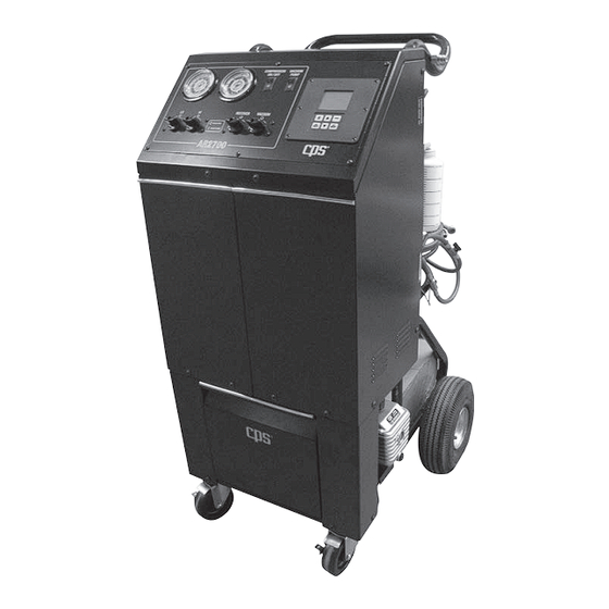
PRO-SET
AR2700 & AR2700M SERIES
®
REFRIGERANT RECOVERY /
RECYCLING SYSTEM
This Equipment has been certified by Underwriters Laboratories Inc.
to meet EPA's minimum requirements for Recovery equipment.
TO BE OPERATED
BY QUALIFIED
PERSONNEL ONLY
OPERATION MANUAL
Advertisement

Subscribe to Our Youtube Channel
Related Manuals for CPS AR2700 Series


Summary of Contents for CPS AR2700 Series
- Page 1 PRO-SET AR2700 & AR2700M SERIES ® REFRIGERANT RECOVERY / RECYCLING SYSTEM This Equipment has been certified by Underwriters Laboratories Inc. to meet EPA’s minimum requirements for Recovery equipment. TO BE OPERATED BY QUALIFIED PERSONNEL ONLY OPERATION MANUAL...
- Page 2 AR2700 & AR2700M SERIES Table Of Contents Specifications Introduction General Safety Instructions Unit Preparation Operation / Pump Down Operation 8-12 Maintenance 13-16 17-18 Parts List AR2700 & AR2700M Specifications AR2700 AR2700A AR2700E Models AR2700M AR2700MA AR2700ME Compressor Type 2/3 HP oil less compressor Dimensions 22"...
- Page 3 Thank you for purchasing the CPS Pro-Set AR2700 & AR2700M series refrigerant ® recovery / recycling / recharge unit. CPS is dedicated to give you the most reliable equipment to meet all your mobile refrigerant recovery/recycling requirements. The following are features of the AR2700: •...
- Page 4 GENERAL SAFETY INSTRUCTIONS Only qualified service personnel should operate this unit. Most states, countries, etc… may require the user to be licensed. Please check with your local government agency. DANGER- The recovery tank used with this unit contains liquid refrigerant. Overfilling of the recovery tank may cause a violent explosion resulting in severe injury or even death.
- Page 5 Plug cable into scale port. Install user (purchased separately) supplied tank onto scale platform. CPS sells CRX50T (50# DOT Tank) and CRX390T (92# DOT Tank) tanks that can be used with this unit.
- Page 6 12. The user pushes the GO/HOLD key again to go to the normal display or turns the machine OFF. The following table are ETW and MRW settings for tanks sold by CPS. Always refer to the tank manufacturers information stamped into the collar of the tank.
- Page 7 UNIT PREPARATION Installing Filter Bracket, Filter Drier Associated Hoses Install Universal Filter / Tank bracket onto top of tank. Use the provided wire ties to hold the Universal Filter / Tank bracket to the collar of the tank. Install filter drier onto Universal Filter / Tank bracket. Use touch fasteners straps to secure the filter drier to the Universal Filter / Tank bracket.
- Page 8 OPERATION Turn main power switch ON. The power switch is located on back left hand corner of unit. The AR2700 LCD will show the current refrigerant amount in storage tank. Open both liquid and vapor tank and hose valves. Manifold Function: Connect HI and LO side service hoses to A/C system.
- Page 9 OPERATION Open the manifold valve (HI an/or LO) to choose the charge path into the car A/C system. 2. Open the oil injection valve. Note: the oil level in the oil injection bottle. 3. Once the required amount of oil has been injected, close injection valve.
- Page 10 CHARGE CONT. / TANK REFILL OPERATION Tank Refill Function: Turn main power switch ON. The power switch is located on back left hand corner of unit. Connect HI side service hoses to refrigerant supply tank. Keep supply tank upright. Open the HI side service hose valve. Open supply tank valve. Push the GO/HOLD key on scale keypad.
- Page 11 PUMP DOWN OPERATION Pump Down Function (AR2700M Series Only) Make sure service hoses are disconnected from AC system. Turn the low and high side manifold valves to the open position. Locate the pump down lever on the back of the machine and move to the Pump Down position (UP) as shown in the picture.
- Page 12 TROUBLE SHOOTING / OPERATION High Pressure Indication - During recovery or tank refill if a high pressure condition trips the HP limit switch, the compressor relay is deactivated, an alarm sounds and the screen shown below is displayed. Solution: Check that both tank valves and both tank hose valves are open.
- Page 13 MAINTENANCE Recycling Maintenance - NCG Purge Procedure It will be necessary to purge the recovery tank of non-condensable gases (NCG’s). The NCG’s are picked up from leaks in a/c systems when performing the Recovery Function. The best time to check for purging is first thing in the morning before using the unit or 30 minutes after the last Recovery operation.
- Page 14 MAINTENANCE Maximum Refrigerant Vapor Pressure Chart (Temp F/C vs. Pressure psig) Temperature Refrigerant Vapor Pressure (psig) R-12 R-134a R-22 R-502 R-404a R-402a R-401a R-407c R-409a 32.0 40.1 37.8 67.5 78.4 82.3 88.3 37.9 68.2 37.6 34.0 41.7 39.5 70.1 81.3 85.4 91.6 39.6...
- Page 15 MAINTENANCE Maintenance- Filter Drier Change Procedure The AR2700 series is equipped with 16 cubic inch filter drier with moisture indicator. This filter should be replaced when the indicator shows Caution or Wet. For the AR2700M series, the Pump Down instructions on page 10-11 can also be used to change the filter.
- Page 16 1 - Exhaust / Refill Cap 2 - Oil Sightglass 3 - Oil Drain Interconnection Hoses, Service Hoses and Coupler Maintenance The AR2700 series uses brass to brass seal type fitting on the ends of the internal interconnecting hoses. No hose gasket maintenance is required on the brass to brass type of connections.
- Page 17 PARTS LIST CPS P/N Description CPS P/N Description 30-784 Low side gauge AR27XHB115 115 volt 300 watt heater blanket 30-785 High side gauge AR27XHB230 230 volt 300 watt heater blanket 39-020 115V 6” fan ARH63-A1 Tank vapor hose 39-021 230V 6” fan...
Need help?
Do you have a question about the AR2700 Series and is the answer not in the manual?
Questions and answers