Advertisement
Quick Links
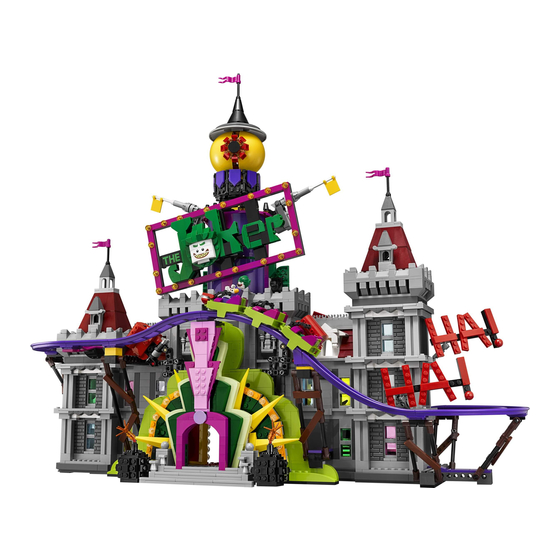
Light My Bricks: LEGO Joker Manor 70922 Lighting Kit
The following page is the instructions for the
Light My Bricks LEGO Joker Manor (70922) LED light kit.
If you run into any issues, please refer to the online troubleshooting guide.
To ensure a trouble-free installation of your light kit, please read and follow each step carefully.
Please note: This page lists instructions for the LED light kit only.
Package Contents:
4x White 30cm Bit Lights
17x White 15cm Bit Lights
12x Flashing White 30cm Bit Lights
Advertisement

Related Manuals for LIGHT MY BRICKS LEGO Joker Manor 70922 Lighting Kit


Summary of Contents for LIGHT MY BRICKS LEGO Joker Manor 70922 Lighting Kit
- Page 1 Light My Bricks: LEGO Joker Manor 70922 Lighting Kit The following page is the instructions for the Light My Bricks LEGO Joker Manor (70922) LED light kit. If you run into any issues, please refer to the online troubleshooting guide.
- Page 2 12x Flashing White 15cm Bit Lights 2x Blue 30cm Bit Lights 4x White 15cm Micro Bit Lights 8x White Strip Lights 1x Green Strip Lights 2x Multi Colour Strip Lights 1x Micro 2-4 Port Expansion Board 3x 6-Port Expansion Boards 3x 8-Port Expansion Boards 3x 12-Port Expansion Boards 1x Flicker Effects Board...
- Page 3 CAUTION: Forcing LEGO® to connect over a cable can result in damaging the cable and light. Connecting cable connectors to Expansion Boards Take extra care when inserting connectors to ports of Expansion Boards. Connectors can be inserted only one way. With the expansion board facing up, look for the soldered “=”...
- Page 4 Installing Bit Lights under LEGO® bricks and plates. When installing Bit Lights under LEGO® pieces, ensure they are placed the correct way up (Yellow LED component exposed). You can either place them directly on top of LEGO® studs or in between. OK, Let’s Begin!
- Page 5 1.) We will start by lighting up the front entrance. First disconnect the cherry bombs on either side as well as the two light sections surrounding the entrance. 2.) Take the left light section and disconnect the following pieces as well as trans clear round plates:...
- Page 6 Take a White 15cm Bit Light and with the cable facing down, place it over the far left stud on this section. Secure the Bit Light in place by reconnecting one of the trans clear round plates over the top. 3.) Repeat previous step to install another 5 x White 15cm Bit Lights to this section as shown below:...
- Page 7 Fold the cables down at the edge of the yellow plates, then reconnect the pieces we removed earlier. Folding the cables down will prevent them from snapping when you reconnect pieces over the top. Ensure the cables underneath plates are laid in between studs. 4.) Take a 12-Port Expansion Board and connect all six cables to it.
- Page 8 Note: If you experience any issues with the lights not working and suspect an issue with a component, please try a different port on the expansion board to verify where the fault lies (with the light or expansion board). To correct any issues with expansion board ports, please view the section addressing expansion board issues on our online troubleshooting guide.
- Page 9 Take a Flicker Effects Board and connect a 5cm Connecting Cable to the IN port. Connect the other end of the cable to the 12-port expansion board. 6.) Take the other of the last 30cm Connecting Cable connected to the 12-port expansion board and thread it through the left side of the entrance space.
- Page 10 Thread the other two 30cm Connecting Cables all the way through the entrance, then hide the expansion board and effects board toward the inside left.
- Page 12 7.) Repeat steps 2- 3 to install another 6 x White 15cm Bit Lights to the right entrance light section.
- Page 13 8.) Take an 8-Port Expansion Board and connect all six bit light cables to it. Take your USB Power Cable and connect it to the expansion board, then connect the other end to your USB Power Bank to test the lights on this side are working OK.
- Page 14 Note: If you experience any issues with the lights not working and suspect an issue with a component, please try a different port on the expansion board to verify where the fault lies (with the light or expansion board). To correct any issues with expansion board ports, please view the section addressing expansion board issues on our online troubleshooting guide.
- Page 15 10.) To make the installation of the lights to the back easier, disconnect the following roller coaster track sections. 11.) Pull out the other end of one of the 30cm Connecting Cables from the left entrance light section (12-port expansion board) and thread it through the space on the right over the fire place.
- Page 16 Take a 6-Port Expansion Board and connect the other end of the 30cm Connecting Cable to it. 12.) Take the other end of the other 30cm Connecting Cable from the left entrance light section (12-port expansion board) and pull it out and thread it over right side of the ceiling technic pieces (grey gears) directly above.
- Page 17 Thread the cable through over the technic pieces (grey gears) on the left side as shown below. Pull the cable down all the way out over the left side behind the first yellow mirror. Take caution when threading the cable over the technic gears. Ensure the cable is laid out of the way of the gear teeth as we don’t want the cable getting caught when we operate the boxing gloves function.
- Page 18 Take a White 30cm Bit Light and thread the connector end of the cable through the top of one of the trans orange round plates with open stud. Thread it all the way through, then carefully bend the LED so that it sits flat against the edge of the stud. Reconnect a trans orange round plate with open stud on top, then connect the remaining trans orange round plate with open stud to the bottom.
- Page 19 Reconnect this spark section to the bomb ensuring the cable is facing away from the spark (toward the right of the bomb) then twist the cable to the left around the sausage piece. Remove the following pieces on the back of the bomb, then lay the cable all the way down before reconnecting the pieces over the top of the cable.
- Page 20 Reconnect this spark section to the bomb ensuring the cable is facing away from the spark (toward the left of the bomb) then twist the cable to the right around the sausage piece. Remove the following pieces on the back of the bomb, then lay the cable all the way down before reconnecting the pieces over the top of the cable.
- Page 21 15.) Take both cherry bombs and thread their Bit Light cable all the way through the side of the entrance underneath the light sections before reconnecting the bombs to the set. Turn the set around to the back, then pull both cables from the cherry bombs all the way out. Connect each cable to the OUT ports on the Flicker Effects Board.
- Page 22 Turn your USB Power Bank ON to test the bomb spark lights are flickering OK. Note: If you experience any issues with the lights not working and suspect an issue with a component, please try a different port on the expansion board to verify where the fault lies (with the light, expansion board, or effects board).
- Page 23 Disconnect the top left pink plate, then take a Flashing White 30cm Bit Light and with the cable facing the left side, place the LED directly over the pink stud. Secure the Bit Light in place by reconnecting one of the trans yellow round plates over the top. Fold the cable underneath the plate then reconnect the plate to the sign ensuring the cable is laid in between studs underneath.
- Page 24 18.) Repeat previous steps install another 5x Flashing White 30cm Bit Lights at the following sections. Ensure the cables are folded underneath each plate facing the inside of the sign before reconnecting them.
- Page 27 19.) Connect the seven flashing lights installed so far to a new 12-Port Expansion Board. Connect the USB Power Cable to the expansion board and connect up the usb power bank. Turn the USB Power Bank ON to test the flashing lights installed so far are working OK. Note: If you experience any issues with the lights not working and suspect an issue with a component, please try a different port on the expansion board to verify where the fault lies (with the light or expansion board).
- Page 28 Disconnect the following pieces from the back of the Joker Sign then lay the next two wires to the right down, before reconnecting the pieces over the top. Ensure all wires are laid in the middle of the pieces and in between studs. 21.) Disconnect the black plate on the left side of the sign.
- Page 29 Repeat the same process to hide and secure the wire on the right side underneath the black plate. Turn the Joker Sign back over. There should be no dangling wires shown.
- Page 30 22.) We will now install flashing lights with shorter cables to the remaining bottom section. Using the same method as above, install 3x Flashing...
- Page 31 White 15cm Bit Lights as per below:...
- Page 33 23.) Turn the Joker Sign over. Secure the following 4 wires underneath the bottom black plate as shown below, ensuring the two on each side are laid in between studs. Take the two lots of wires and twist/wind them around each other all the way to their ends so they come together to form one larger cable.
- Page 34 24.) Disconnect the black plate on the right side, then lay the six wires down in between studs before reconnecting the black plate over the top. Group the six wires and twist/wind them around each other all the way to their ends so they come together to form one larger cable.
- Page 35 25.) Take the 12-Port Expansion Board from step 18 and connect the four light cables on the left side to it. Once connected, twist/wind the excess cablesaround each other as shown below: Connect the six light cables from the right side to the expansion board, then connect up the USB Power Cable to connect to your USB Power Bank. Turn on the power bank to test all 10 flashing lights are working OK.
- Page 36 Note: If you experience any issues with the lights not working and suspect an issue with a component, please try a different port on the expansion board to verify where the fault lies (with the light or expansion board). To correct any issues with expansion board ports, please view the section addressing expansion board issues on our online troubleshooting guide.
- Page 37 27.) Disconnect the following sections on top of the giant eyeball then disconnect the black cone piece at the bottom of it. Take a White 15cm Bit Light and thread the connector end of the cable through the top of the black cone piece. Gently bend the LED so that it sits flat against the edge of the stud, then secure the Bit Light in place by connecting a provided Trans Clear Round Plate 1×1 over the top.
- Page 38 28.) Pull the other end of the 30cm Connecting Cable from previous step up behind the Joker Sign then connect it to a White Strip Light. Connect the White 15cm Bit Light from above the giant eyeball to the right port on the strip light. Using it’s adhesive backing, stick the Strip Light underneath the roof of the giant eyeball in the below position so that it shines down onto the eye.
- Page 39 Connect the USB power cable (connected to power bank) to the 12-Port Expansion Board on the back of the set (as per step 9). Turn ON the USB Power Bank to test all the lights installed to the front of the Joker Manor are working OK. Note: If you experience any issues with the lights not working and suspect an issue with a component, please try a different port on the expansion board to verify where the fault lies (with the light or expansion board).
- Page 40 29.) Turn the entire set around to the back as we will now light the inside of the Joker Manor starting with fire place. Using your LEGO removal tool,remove the flame section at the brown plate, then disconnect the flame pieces. Take a White 15cm Micro Bit Light and with the cable facing the back and led facing up, place it over the following stud.
- Page 41 30.) Turn the fireplace section around, then lay the cables toward the right side. Secure them together by twisting them around each other a few times inthe right corner, then turn the section around and secure the cables underneath the angled tile on the left side as shown below: Reconnect the fireplace section ensuring the cable is laid toward the left side in between pieces.
- Page 42 Micro 2-4 Port Expansion Board. The micro bit light connectors only connect to the expansion Connect the four Micro Bit Lights to the board port one way. Follow the below image guides to ensure you connect the micro bit lights correctly to the expansion board. 31.) Take a 5cm Connecting Cable and connect it to the larger port on the Micro Expansion Board then bring everything over the mirror on the left side.
- Page 43 Turn your USB Power Bank ON to test all lights in the fire place are lit and flickering OK. Note: If you experience any issues with the lights not working and suspect an issue with a component, please try a different port on the expansion board to verify where the fault lies (with the light, expansion board, or effects board).
- Page 44 32.) Disconnect the first mirror, then disconnect the brown plate with yellow tile on top of the second mirror. Neatly lay the four micro bit ligiht cables in between studs before reconnecting the brown plate with yellow tile over the top. Group all the components together and push them to right side before reconnecting the first mirror to hide them behind.
- Page 45 Disconnect the second mirror from the left side, then tuck the 30cm connecting cable (leading to the 12-port expansion board on the left) inside and behind the yellow 1×2 plate with bar before reconnecting the mirror over the top. 33.) Slightly disconnect the following grey brick, then using your LEGO Removal Tool, completely disconnect the top section as shown below:...
- Page 46 Take a 15cm Connecting Cable and connect one end to the next port on the 6-Port Expansion Board at the very bottom. Pull the other end of the connecting cable up and thread it through the inside of the theatre room and to the top. Pull the cable all the way out from above and connect it to a new 6- Port Expansion Board.
- Page 47 34.) We will now install a Bit Light underneath the top of the arch window. First take out a White 15cm Bit Light and with the LED facing down and cable to the right, place it in the centre of the base of a provided Trans Clear Plate w Rounded Bottom 2×2. Connect the trans clear plate underneath the following red bricks in the below position, ensuring the Bit Light is securely in the middle of the trans clear plate.
- Page 48 Disconnect the grey roof piece and fold the cable underneath it. Reconnect it ensuring the cable is laid in between studs. Disconnect the grey tile on the right side, then lay the cable down in between studs. Ensure you push the cable in the corner before reconnecting the tile over the top.
- Page 49 Bring the cable down the right side of the roof, then disconnect the following angled brick. Lay the cable in between studs, and push the cable down in the corner to ensure you have enough cable slack before reconnecting the brick over the top. This will prevent the cable from snapping when you reconnect the angled brick.
- Page 50 37.) Turn this roof section onto it’s front so we can access underneath. Take a White Strip Light and connect a 5cm Connecting Cable to the right port. Using it’s adhesive backing, stick the strip light underneath this section in the below position ensuring the 5cm cable is facing the right. Bring this section over the top of the building and connect the other end of the 5cm Connecting Cable to the 6-Port Expansion Board underneath.
- Page 51 38.) Ensure all cables are neatly laid in between studs and that all components are neatly placed inside the building before reconnecting the roof and surrounding pieces. Secure the 15cm Connecting Cable dangling down the side of the theatre room behind the theatre screen as shown below: Turn the USB Power Bank ON to test the lights installed to the right section are all working OK.
- Page 52 Note: If you experience any issues with the lights not working and suspect an issue with a component, please try a different port on the expansion board to verify where the fault lies (with the light or expansion board). To correct any issues with expansion board ports, please view the section addressing expansion board issues on our online troubleshooting guide.
- Page 53 Take out the 2x Multi Colour Strip Lights and using it’s adhesive backing, stick one to each of the LEGO spot lights (on the flat side of the 2×6 plate). Ensure that the port on one of the strip lights is facing the right side for one of the spot lights, and the port on the other strip light is facing the left side for the other spot light (upside down).
- Page 54 41.) Take another 30cm Connecting Cable and connect one end to the other Spot Light. Connect the other end of the cable to a spare port on the 12port expansion board on the bottom of the left section of the building. Bring the spot light through the following space leading to the front, then place it at the front right of the building.
- Page 55 Turn the set around to the front and turn ON the USB Power Bank to test the spot lights are working and changing colours OK. The spot lights should be positioned so they are projecting up along the walls. 42.) Turn the set around to the back again and using your LEGO Removal tool, create a gap underneath the brown plate above the ground floor on theleft side of the set.
- Page 56 Connect a new 15cm Connecting Cable to the strip light’s right port, then using it’s adhesive backing, stick the white strip light underneath the brown plate above the ground floor in the following position (upside down). Ensure the 15cm cable that is connected to the 12-port expansion board is on the left side.
- Page 57 Note: If you experience any issues with the lights not working and suspect an issue with a component, please try a different port on the expansion board to verify where the fault lies (with the light or expansion board). To correct any issues with expansion board ports, please view the section addressing expansion board issues on our online troubleshooting guide.
- Page 58 Using it’s adhesive backing, stick the white strip light underneath the white plate above the recording studio in the following position. Loop the excess cable from the right cable next to the strip light, then turn ON the USB Power Bank to test the two strip lights are working OK. 44.) Tuck the cable from the left side in between the first and second stud in between floors before pushing down the white plate on the left side to closeup the gap.
- Page 59 45.) Connect the other end of the 15cm connecting cable we brought up from the second floor to the left port on a new White Strip Light. Take a new 15cm Connecting Cable and connect it the strip light’s right port. Using your LEGO Removal tool, create a gap underneath the brown plate above the third floor (swimming pool) to allow you to slightly lift up the front side of the attic section.
- Page 60 Turn your USB Power Bank ON to test all the strip lights are working OK. Note: If you experience any issues with the lights not working and suspect an issue with a component, please try a different port on the expansion board to verify where the fault lies (with the strip light or expansion board).
- Page 61 Take the other end of the 15cm Connecting Cable from below and connect it to a 6-Port Expansion Board. 47.) We will now install a Bit Light to shine down just above the arch window (similar to the one on the right side in step 34). Take out a White 15cm Bit Light and with the LED facing down and cable to towards you, place it in the centre of the base of a provided Trans Clear Plate w Rounded Bottom 2×2.
- Page 62 Use your LEGO Removal Tool to create a gap in between the red and grey bricks above to allow you to thread the Bit Light cable through this space. Pull the cable all the way out from the other side before closing up the gap ensuring the cable is laid in between studs. 48.) Bring the Bit Light Cable over the wall to the left, while securing it down (both bit light cable and connecting cable) underneath the following twogrey tiles.
- Page 63 Reconnect the top left wall section over the two cables ensuring they are also laid in between studs underneath before connecting the Bit Light cable to the 6-Port Expansion Board. Turn ON the USB Power Bank to test the Bit Light is working OK. Note: If you experience any issues with the lights not working and suspect an issue with a component, please try a different port on the expansion board to verify where the fault lies (with the strip light or expansion board).
- Page 64 49.) Take the roof section and disconnect the flag pole. Take a White 30cm Bit Light and with the cable on the left side, place it over the stud on the roof. Secure it in place by connecting a provided Trans Clear Round Plate 1×1 over the top. Reconnect the flag pole, then bring the wire down the left side of the roof and secure it underneath the grey tile.
- Page 65 50.) Use the LEGO Removal tool to disconnect the roof at the following section. Take a White 15cm Bit Light and with the cable on the left and the LED facing down, place the Bit Light in the middle of this section. Reconnect the roof to secure the bit light and cable in place ensuring the cable underneath is laid in between studs.
- Page 66 Fold both cables underneath, then bring this section over the attic. Connect both bit light cables to the 6-port expansion board below, then place neatly place components underneath (behind the boxes) before reconnecting the roof section. Turn the USB Power Bank ON to test all lights in the top section are working OK.
- Page 67 51.) Take a new 30cm Connecting Cable and connect it to a spare port on the 12-Port Expansion Board on the bottom of the left side. Bring the other end of the cable over to the right and thread it through the following technic pin. Pull the cable out from the other side. Take 2x White Strip Lights and connect them together using a 5cm Connecting Cable.
- Page 68 Ensure there are no dangling cables inside the entrance area, then reconnect the flower section that turns the gears for the boxing gloves 52.) Pull the 30cm Connecting Cable back out from the left beam, then bring it around to the right and secure it in between the mirror and beam.
- Page 69 Pull the other end of the 15cm Connecting Cable all the way out from the right beam then thread it through the technic pin above that leads into the second level. Pull the cable all the way out, then connect it to a new 8-Port Expansion Board. Remove the “Jokes” Box. 53.) We will now install some flashing lights to the purple arrow sign.
- Page 70 Take a Flashing White 30cm Bit Light and with the cable facing the right, place it over the following stud. Secure the light in place by reconnecting one of the trans pink round plates over the top. 54.) Following the same method used in the previous step, install another 2x Flashing White 30cm Bit Lights to this section.
- Page 71 Take the purple and black plates and install another 2x Flashing White 30cm Bit Lights to them ensuring both cables are facing up. Fold both cables down underneath the plates before reconnecting this section back to the arrow sign. Reconnect the technic gear bar to the back of the sign then connect all five bit light cables to the 12-port expansion board on the bottom left. Turn ON the USB Power Bank to test the flashing lights are working OK.
- Page 72 55.) Disconnect the bit lights from the expansion board, then take the two left cables and thread them up the space in between plates as shown below.Pull the two cables all the way out from the top side, then thread them back down the next space in between plates. Pull the two cables all the way out from below.
- Page 73 Take 3x Adhesive Squares and stick them to the base of the 12-Port Expansion Board at the bottom of the left side of the building. Mount the expansion board underneath the base plate in the below position. 57.) We will now light up the blue arrow sign on the second level. Disconnect this section and remove the technic gear bar from the back, thendisconnect the following pieces from the front.
- Page 74 58.) Following the same method used to install lights to the purple arrow sign, install 5x Flashing White 15cm Bit Lights to the blue arrow sign (steps 53-55). Thread the two left cables through the bottom middle of the plates, then back down before connecting them to the 8-port Expansion board in previous step (step 56).
- Page 76 Disconnect the cables from the 8-port Expansion Board, then twist and wind all five cables around each other all the way to the ends so they all come together to form one large cable. 59.) Reconnect the blue arrow sign to the set, then thread the cable behind the sign toward the left and reconnect the five lights to the 8-port expansionboard.
- Page 77 Tuck the 8-port expansion board from the right side of the joker slide into the space to the left before reconnecting the Jokes box. 60.) We will now light up the BAM! sign. Remove this section and disconnect the trans light blue round plates from it.
- Page 78 Take a Flashing White 15cm Bit Light and with the cable facing down, place it directly over the left stud. Secure the light in place by reconnecting one of the trans light blue round plates over the top. 3 x Flashing White 15cm Bit Lights to the BAM! sign. Repeat this process to install another...
- Page 79 61.) Connect the four lights into the 8-port expansion board on the left side of the joker slide, then turn ON the USB Power Bank to test the lights areworking OK. Note: If you experience any issues with the lights not working and suspect an issue with a component, please try a different port on the expansion board to verify where the fault lies (with the strip light or expansion board).
- Page 80 Reconnect the BAM! sign and reconnect the four cables to the 8-port expansion board. Turn the USB Power bank on again to test all the flashing lights are working OK. 62.) We will now install lights above the eyes of the Joker slide. Disconnect the following hair sections from each side, then using a LEGO Removal Tool, create gaps just underneath the eyebrows to allow you to disconnect the front end of the top section as shown below.
- Page 81 Take 2x Adhesive Squares and stick each one to the back of each Blue Bit Light. Stick each Blue Bit Light underneath the eyebrow sections in the middle of the black eyebrow plates. Pull the other end of the cables down the slide, then reconnecting the top section. 63.) Thread the other end of the cables back through the inside of the slide through the left side.
- Page 82 Note: If you experience any issues with the lights not working and suspect an issue with a component, please try a different port on the expansion board to verify where the fault lies (with the strip light or expansion board). To correct any issues with expansion board ports, please view the section addressing expansion board issues on our online troubleshooting guide.
- Page 83 64.) Take a White Strip Light and connect a 15cm Connecting cable to the left port. Thread the other end of the 15cm Connecting Cable through the gap in the top left corner just underneath the Joker teeth. Pull the cable all the way out from behind the left side until the Strip Light touches the corner, then connect the other end of the cable to the remaining port on the 8-Port Expansion Board.
- Page 84 Neatly tuck the 8-port expansion board and cables on the left side of the Joker Slide inside the space to the right before reconnecting the Evil Plans Box. Use tape to secure the Bit Light cables from the BAM! sign to the wall. Turn ON the USB Power Bank to test the White Strip Light just above the Joker slide is working OK.
- Page 85 Note: If you experience any issues with the lights not working and suspect an issue with a component, please try a different port on the expansion board to verify where the fault lies (with the strip light or expansion board). To correct any issues with expansion board ports, please view the section addressing expansion board issues on our online troubleshooting guide.
- Page 86 Using it’s adhesive backing, stick the Green Strip Light underneath the pink plates as shown below. Pull the excess 30cm Connecting Cable back out the right side. Pull the cable down, then wind it around the two black technic pins where the hair section connects to.
- Page 87 Reconnect the left and right hair sections, then secure the excess cable down the right side of the Joker face using tape. 66.) Finally, reconnect all the sections which make up the roller coaster tracks, which we removed earlier back in step 10. Turn the USB Power Bank ON to test that all lights are working OK.
- Page 88 (with the strip light or expansion board). To correct any issues with expansion board ports, please view the section addressing expansion board issues on our online troubleshooting guide. Congratulations, this finally complete’s installation of your Light My Bricks Joker Manor Light Kit. We thank you for purchasing this product and hope you enjoy!
Need help?
Do you have a question about the LEGO Joker Manor 70922 Lighting Kit and is the answer not in the manual?
Questions and answers